Download presentation
Presentation is loading. Please wait.

2
GE Plastics Engineering Plastic Injection Molding e

3
e GE Plastics Korea 曺 武 植 부장 / 기술 써비스 한국 GE(U.S.A) 프라스틱스 ( 주 ) 서울 강남구 논현동 231-8 ( 우 )135-010 Tel: 02-510-6212 Fax:02-510-6420 E-mail: Moo-Sik.Cho @gep.ge.com
 프라스틱스 ( 주 ) 서울 강남구 논현동 ( 우 ) Tel: Fax:")
4
Injection Molding Introduction 사출성형은 복잡하거나 고품질이거나 치수가 엄격한 제품의 2 차 가공을 최소화하면서 대량생산을 가능하게 한다.

5
Injection Molding Introduction 리브, 보스, 홀 등이 있는 복잡한 제품

6
Injection Molding Introduction 대형 제품 : 자동차 Bumper / Fender

7
Extrusion 압 출압 출 Pellets Part Heating Coils Screw Die Continuous Process

8
The Profile Extrusion Die Continuous Flow Uniform Cross-Section Extrusion

9
Extrusion Extruded Through Die Supported and Cooled by a Stack of Polishing Rolls Cut and Trimmed Once Below Glass Transition Temperature Sheet May be Used in Thermoforming and Compression Molding Sheet Extrusion Die Extrusion Cutaway View Rigid Sheet Roll Stack

10
압축 성형 (Compression Molding) Softened sheet is placed in a mold then pressed into shape by compressive force.
 Softened sheet is placed in a mold then pressed into shape by compressive force.")
11
Compression Molding 23 1 Soft Sheet Trimming Compressive Force Part

12
Thermoforming 진공 성형 (Vacuum Forming) Atmospheric Pressure(14.7 psi) Softened Sheet Mold Part Vacuum
 Atmospheric Pressure(14.7 psi) Softened Sheet Mold Part Vacuum")
13
중공 성형 (Blow Molding)
")
14
Pinch Bar Parison Drop Pre Blow Full Pressure Release 중공 성형 (Blow Molding) Mold Part 1 2 3 4 5
 Mold Part")
15
Injection Molding 발포 성형 Increases the attainable wall thickness Gas expands inside plasticized material to create foam core SKIN CORE

16
Injection Molding LEXAN FOAMABLE RESIN Business Machine Chassis 발포성형 (Structural Foam Part) High Strength and Rigidity in Larger Parts
 High Strength and Rigidity in Larger Parts")
17
Injection Molding 발포 성형 대형 제품 가능 저압 성형 가능 High Stiffness to Weight Ratio AdvantagesDisadvantages 사이클 타임 길다 외관 발포제 blending 필요 Blowing Agent with Resin

18
Injection Molding Gas Assist Molded RibInjection Molded Rib Gas Created Cavity Sink Gas Assist Injection Molding

19
Compression Preset Gap Injection f =0=0 G o ICM Process ( 사출 압축 성형 ) Sequential ICM
 Sequential ICM")
20
Compression Preset Gap GfGf = 0 G GoGo Injection Selective ICM or Coining ICM Process Thinner wall, 중량 감소 잔류응력 감소 충격강도 우수 Advantages Low warpage, 치수 안정성

21
Injection Molding Introduction GOOD PART 원 료원 료금 형 성형 공정 제품의 디자인

22
Injection Molding Introduction 높은 생산성 / 대량생산 가능 노동비 절감 자동화가 용이 2 차 가공의 최소화 Molded-in Inserts 가능 Glass, Carbon, etc. Fillers 복잡한 제품도 성형 가능 Good Decoration 가능 사출 성형의 장점

23
Injection Molding Introduction 고가의 금형비 고가의 성형기 및 주변기기 고압 공정 사출 성형의 단점

24
Injection Molding

25
사출 성형 공정

26
Injection Molding Process 사출성형 공정 순서 : 원료 건조 사출기에 원료 투입 계량 금형의 캐비티로 용융수지 사출 냉각 및 고화 금형으로부터 제품 취출

27
Injection Molding Process 엔지니어링 플라스틱은 원료 제조 공정, 원료 이동 및 저장 중에 수분이 흡수된다. 수지 건조 G E P l a st i c s

28
Injection Molding Process 건조가 불충분한 경우 :

29
Injection Molding Process 건조가 불충분한 경우 : 제품의 외관 불량 및 물성 저하의 원인이 된다..

30
Injection Molding Process 건조가 불충분한 경우 : 제품의 외관 불량 및 물성 저하의 원인이 된다. 연속 작업시 동일 성형조건에서 재현성이 어렵다.

31
Injection Molding Process H2OH2OH2OH2OH2OH2O Drying Removes Moisture 건조된 대기에 펠렛이 노출되어 있으면 펠렛으로부터 수분이 빠져 나간다.

32
원료별 건조 조건 원료별 건조 조건 Lexan 120 - 125 ℃ X 3 - 4 시간 Valox 120 ℃ X 3 - 4 시간 Ultem 150 ℃ X 4 - 6 시간 Xenoy 110 - 120 ℃ X 3 - 4 시간 Noryl 열변형 온도보다 10-20 ℃ 낮게 X 2 - 4 시간

33
건조 후 적정 수분 함량 Lexan / Xenoy /Cycoloy 0.02 % 이하 Valox 0.02 % 이하 Ultem 0.05 % 이하 Injection Molding Process

34
건조기 추천 사양 Hopper 용량 : Hopper 내에서의 체류 시간이 3 - 4 시간 이상 일 것. 실제의 건조온도는 에어가 들어 가는 입구의 온도가 감지될 것. Hopper 입구로 들어가는 에어의 상태 : Dew point -29 - -40 ℃ Closed Loop 타입의 제습형 건조기 사용. Air 량 : (1 ft*3 / min.) /lb / hr Injection Molding Process
 /lb / hr Injection Molding Process.")
35
건조기 Hopper 용량 1 회 사출중량 / Cycle Time 시간당 사출중량 예 : 1 kg( 제품 +S/R) 30 초 Cycle= 2 kg/ 분 = 120 kg/ 시간 시간당 사출중량 x 건조시간 = 최소 호파 용량 예 : 120 kg/ 시간 x 4 시간 = 480 kg 이상 용량의 Hopper The Hopper should be sized large enough to provide adequate resin residence time. Injection Molding Process 1 회 사출중량 (kg) X 3600 X 건조시간 싸이클타임 ( 초 )
 X 3600 X 건조시간 싸이클타임 ( 초 ).")
36
Drying Polymers Moisture Content 상대 습도 @ 23 o C Relative Humidity describes the percent of moisture present in the air relative to the greatest amount that could be held at a given temperature.

37
Drying Polymers Moisture Content 상대 습도 @ 32 o C 20% Relative Humidity @ 10 o C 100% Relative Humidity @ 23 o C 50% Relative Humidity

38
Drying Polymers Moisture Content Condenses at 1 o C Condenses at 12 o C Condenses at 23 o C 이슬점 (Dew Point) 공기중의 수분이 응축되기 시작할 때의 온도
 공기중의 수분이 응축되기 시작할 때의 온도")
39
Drying Polymers Moisture Content Pellet Moisture Absorption Dew Point of 1 o Dew Point of 12 o Dew Point of 23 o The Higher the Dew Point, the More Moisture in the Air The More Moisture in the Air, the More Water Absorbed by the Pellets

40
TVI 건조 확인 Test TVI 건조 확인 Test (Tomasetti Volatile Indicator) 1. 핫플레이트에 전원을 연결하고 유리슬라이드 2 장을 올려 놓고 적정온도를 설정 후 1 - 2 분 기다린다. * 노릴, 렉산 : 290 ℃ 바록스, 지노이 : 250 ℃ 울템 : 350 ℃ 2. 2 분후 유리슬라이드가 충분히 가열되었을 때 핀셋으로 측정할 원료 펠렛을 3 - 4 개 슬라이드 위에 올려 놓는다. 3. 다른 슬라이드로 덮어 샌드위치로 만든다. 4. 펠렛의 직경이 약 13mm 될때 까지 위에서 누른다. 5. 핫플레이트에서 샌드위치된 슬라이드를 꺼내어 검사한다.

41
Drying Polymers Moisture Content There are several test methods to verify moisture content such as the Karl Fischer Titration Test and the Tomasetti Volatile Indicator (TVI)
")
42
Drying Polymers Drying Rates Drying to OK Level 건조 효율을 극대화하기 위해서는 제습건조기의 이슬점은 적어도 -29 o C 가 되어야 한다. Dry Air -29 o C Dew Point

43
Drying Polymers Drying Rates Drying Precautions 건조 온도 : 너무 낮을 경우 - 건조 부실 높을 경우 - 수지의 물성 저하 혹은 수지 엉김 현상 발생 건조 시간 : 너무 짧다 - 건조 부실 너무 길다 - 수지의 물성 저하

44
Drying Polymers Dryer Efficiencies 건조 방법 Oven Dryer with Trays Effective for Small Batches Hopper Dryer Preferable for Longer Runs

45
Drying Polymers Dryer Efficiencies 열풍 건조기 (Hot Air Dryers) Pump Heater Hopper Exhaust Dew point 는 변하지 않고 상대습도만 낮추어 준다. Ambient Air

46
Drying Polymers Dryer Efficiencies Hopper Blower Processing Desiccant Bed Reactivating Desiccant Bed Processing Air Heater A blower forces air through the desiccant bed to lower its dew point, through the heater to raise its temperature, and into the hopper to dry the pellets. 제습 건조기 Dry Air Wet Air

47
Drying Polymers Dryer Efficiencies Just as pellets can become saturated, the desiccant beads can become saturated and therefore have to be periodically reactivated. Hopper Blower Reactivating Desiccant Bed Processing Desiccant Bed Processing Air Heater Blower Heater Filter

48
Drying Polymers Dryer Efficiencies Desiccant Beads 15 o C Dew Point-29 o C Dew Point Desiccant Beads The ceramic desiccant beads have such a strong affinity to water that they will absorb enough moisture from the air to achieve a dew point of at least -29 o C.

49
Drying Polymers Dryer Efficiencies Dryer Air Fast Moving Pellets Slow Moving Pellets Spreader Constant Pellet Movement Dryer Air Preferred Hopper Design Hoppers that are twice as high as they are wide (aspect ratio of 2:1) improve dryer efficiency. A spreader will prevent channeling and aid air flow

50
Injection Molding Process Model of Amorphous Polymers Adding Heat Increases Space Between Molecular Chains Raise Temperature of Polymer T G Locked Entanglements Stiff Flow Easier Flow Raise Temperature of Polymer

51
Injection Molding Process 가열 및 수지의 용융 스크루 회전에 의해 마찰열이 발생 배럴에 감겨진 히터 밴드에 의해 수지에 열 전달 Heater Coils on the Screw Barrel

52
적정 스크루 회전속도 스크루의 회전속도는 스크루의 직경에 따라 달라지는 것이 좋다. 적정 RPM = 8 X 25.4 X 60 스크루직경 (mm) X 3.14 예 ) 90mm 스크루 경우 : 8 X 25.4 X 60 / 90 X 3.14 = 43 RPM Injection Molding Process
 X 3.14 예 ) 90mm 스크루 경우 : 8 X 25.4 X 60 / 90 X 3.14 = 43 RPM Injection Molding Process.")
53
Injection Flow

54
Injection Molding Process Injection Flow

55
Injection Molding Process Injection Flow

56
Injection Molding Process Injection Flow

57
Injection Molding Process 제품 냉각 및 고화 용융수지 냉 각냉 각 완성품

58
Injection Molding Process 1 2 3 제품 이형 2단 금 형2단 금 형 이젝트핀에 의한 이형

59
Injection Molding Process 사출 압력 HydraulicPressureHydraulicPressure Time 충진시간 계량 시간 배 압

60
Injection Molding Process 사출성형의 주요 성형 조건 용융 온도 금형 온도 실린더 온도 스크루 RPM 사출 속도 사출 압력 보압 배압 형체력 쿠션

61
Injection Molding Variables 용융 온도 35 30 25 20 15 10 5 0.030.060.090.120.150.180.210.240 Wall Thickness in Inches M e l t F l o w (in.) LEXAN?101 288 deg C. 101 @ 315 deg. C 용융온도를 올리면 흐름길이는 늘어 난다. 그러나 용융온도를 과도하게 올리면 물성이 떨어지므로 주의 해야 한다.

62
Injection Molding Variables 금 형 온 도 금형온도는 제품의 냉각에 중요한 영향을 미친다. 균일한 금형온도는 제품의 휨 방지에 효과가 있다. 일반적으로 냉각수 라인을 통하여 금형온도가 조절된다 ( 물 혹은 Oil 사용 ).
..")
63
Injection Molding Variables 실린더 온도 분포 Nozzle Zone Adapter Zone Front Zone Center Zone Rear Zone 노즐부와 전부의 온도는 용융온도를 유지할 정도로 온도룰 설정한다. 후부 온도는 낮게 설정하여 수지가 배럴에 고착되어 스크류 회전시 전단열이 발생되게 한다.

64
Injection Molding Variables 수지의 실린더내 정체 시간 Lexan : Max.8 분 Xenoy: Max.5 분 Valox : Max.6 분 Ultem : Max.15 분 To measure this, colored pellets are dropped into the base of the hopper. Time is measured until the point when colored extrudant is purged from the nozzle. 용융수지가 스크루 내에서 머무르는 시간. 실린더용량 (g) X 2.5 X 사이클타임 제품중량 (g)
 X 2.5 X 사이클타임 제품중량 (g).")
65
Injection Molding Variables 형 체 력 투영면적 ( ㎠ ) X 350 - 500 : 일반그레이드 1000 400 - 600 : 강화 그레이드 사출 압력 형체 압력 형체력이 부족하면 성형품에 플레쉬가 발생
 X : 일반그레이드 : 강화 그레이드 사출 압력 형체 압력 형체력이 부족하면 성형품에 플레쉬가 발생")
66
Injection Molding Variables 쿠 션 (Cushion) Cushion 사출이 완료된 후에도 베럴 앞쪽에 용융수지가 남아 있는 것을 말 하는데 성형 시 캐비티에 충분한 보압을 주기 위하여는 적당한 양의 쿠션이 필요하다. 적정 쿠션량 : 3 - 5mm * 쿠션량이 너무 많으면 정체시간이 길어짐.

67
Injection Molding 사출 장비

68
Injection Molding Equipment 사출부 형체부 스크루 배럴

69
Injection Molding Equipment Hydraulic Injection Cylinders

70
Injection Molding Equipment The Screw Barrel 수지를 용융 용융수지를 금형의 캐비티로 사출

71
Injection Molding Equipment Barrel Unit The Reciprocating Screw (Filling) Throat Heating Coils Nozzle Hopper Screw Barrel Force, Torque From Injection Unit
 Throat Heating Coils Nozzle Hopper Screw Barrel Force, Torque From Injection Unit")
72
Injection Molding Equipment Barrel Unit The Reciprocating Screw 스크루가 회전하면서 뒤로 후퇴함에 따라 수지가 용융되면서 배럴의 앞 쪽으로 모이게 된다. Shot Rotation and Back Pressure

73
Injection Molding Equipment Barrel Unit The Reciprocating Screw 사출 직전 용융수지가 스크루의 앞 쪽에 모인 상태 Shot Injection Pressure

74
Injection Molding Equipment Barrel Unit The Reciprocating Screw Screw Pushes Forward: Inject Cushion Packing Pressure

75
Injection Molding Equipment - Screw 계량부 압축부 공급부 공급부 : 수지를 받아 들여 압축부 쪽으로 이동 시킴 압축부 : 첸널의 깊이가 계량부로 감에 따라 얕아 지면서 수지를 압축하여 전단열을 발생시키고 섞여 있는 에어를 최소화하면서 수지를 용융 시킨다. 계량부 : 용융수지를 최종적으로 가소화 시킴.

76
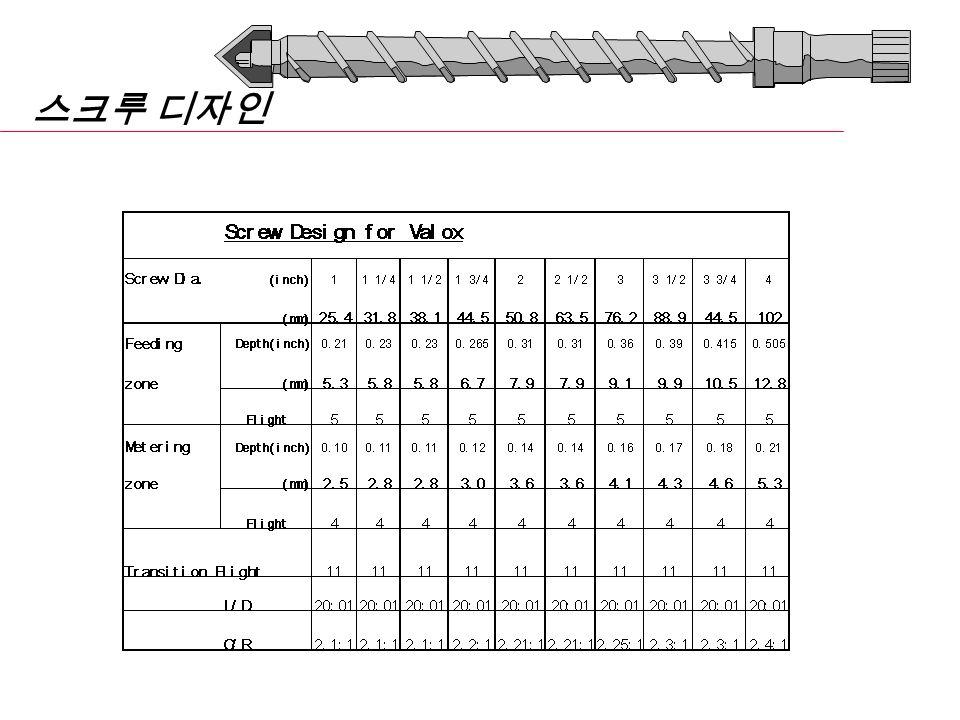
Injection Molding Equipment - Screw MeteringFeed Screw and Cylinder Design hfhf hmhm L/D = 20:1 압축비 = h f / h m = 2.5:1 스크루 산 수 : 공급부 5, 압축부 11, 계량부 4 Cylinder bi-metallic for Abrasion Resistance Transition L D

77
스크루 디자인

80
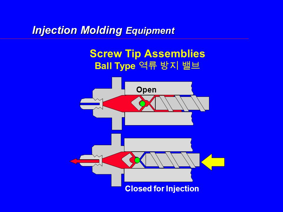
Injection Molding Equipment Screw Tip Assemblies Ball Type 역류 방지 밸브 Open Closed for Injection

81
Injection Molding Equipment Reciprocating Screw Tip Assemblies Check Ring Type Nonreturn Valve 스크루 회전시 첵크링이 열려서 용융수지가 앞에 모임 사출시 첵크링이 닫혀서 용융수지의 역류를 방지 첵크링 타입의 밸브가 좋다.

82
Check Ring Design Screw Head 와의 간격 : Screw 계량부 단면적의 최소 80% 이상 이동 거리 : 최소 4.76mm ( 직경 65mm 이하의 Screw 경우 )
")
83
Injection Molding Equipment 실린더 노즐 Heating Band Cylinder Bore To Mold 최소 치수 : 노즐 경 ; Min. 5.0mm ( 금형 스프루보다 0.5 - 1.0mm 작게 ) 랜드 길이 ; Min. 5.0mm 노즐 Bore ; Min. 13 mm
 랜드 길이 ; Min. 5.0mm 노즐 Bore ; Min. 13 mm.")
84
Injection Molding Tooling 금 형

85
Injection Molding Tooling 2 단 금 형 Exploded View "B" Plate "A" Plate Top Clamping Plate Ejector Housing Support Plate Elector Retainer Plate Ejector Plate Leader Pin Return Pin PARTING LINE

86
Injection Molding Tooling 2단 금 형2단 금 형

87
12 34

88
Support Plate Ejector Retainer Plate Ejector Plate Ejector Housing "B" Plate "X" Plate "A" Plate Top Clamping Plate 3단 금 형3단 금 형 PARTING LINE

89
Injection Molding Tooling 3 단 금형 1 2 3 4 5

90
Injection Molding Tooling Sprue Bushing Nozzle Radius Orifice

91
Sprue Puller REVERSE TAPER BEST Z PULLER GOOD GROOVE TROUBLE- SOME SUCKER PIN NOT RECOMMENDED Injection Molding Tooling

92
Runner Systems 런너는 스프루에서 게이트로 용융수지를 이동시킨다.

93
Material Flows Only Through Molten Portion of Runner Outer Skin Chills on Contact with mold Surface Runners Flow

94
Injection Molding Tooling Gating Direct Sprue Fan Edge Tab Disk Pin Point

95
Injection Molding Tooling Manifold Recommendations Passages Externally Heated (4 Heaters) Bore Size 12.7mm or Larger 50 Watts/in 3 Minimum
 Bore Size 12.7mm or Larger 50 Watts/in 3 Minimum")
96
Injection Molding Tooling Hot Runner Systems Cavity Plate = 50 0 Manifold = 260 0 핫런너의 장점 사이클 단축 - 15-20% 원료 절감 - No Sprues or Runners 제품 품질 향상 - 스트레스 감소

97
Injection Molding Tooling 가스 빼기 (Venting) Gate Parting Line Vents 사출시 캐비티에 갇힌 가스를 배출 탄자국 (Burn Marks) 방지 벤트 위치 : 파팅 라인 이젝트 핀 런너 끝단 벤팅 핀
 Gate Parting Line Vents 사출시 캐비티에 갇힌 가스를 배출 탄자국 (Burn Marks) 방지 벤트 위치 : 파팅 라인 이젝트 핀 런너 끝단 벤팅 핀")
98
Tooling Venting Clearance Around Knockout 0.04mm Ejector Pin

99
금형의 가스 빼기 금형의 가스 빼기 원재료 깊이 폭 랜드길이 (mm) 렉산 일반그레이드 0.04 - 0.06 10 - 20 5 - 10 렉산 강화그레이드 0.05 - 0.07 " " 노릴 일반그레이드 0.03 - 0.05 5 - 10 5 - 10 노릴 강화그레이드 0.04 - 0.06 " " 바록스 일반그레이드 0.01 - 0.02 4 2.5 바록스 보강그레이드 0.02 - 0.04 " " 울템 0.04 - 0.2 3 5
 렉산 일반그레이드 렉산 강화그레이드 노릴 일반그레이드 노릴 강화그레이드 바록스 일반그레이드 바록스 보강그레이드 울템")
100
Injection Molding Material Material Considerations

101
Injection Molding Material Thermoplastics and Degradation 과 열 구 역과 열 구 역 온도온도 시 간시 간

102
Injection Molding Material 플라스틱의 수축율 V part V mold l part l mold S l = l mold - l part l mold S v = v mold - v part v mold or

103
Injection Molding Material Shrinkage and Injection Molding Simplified Pressure History - Injection Molding Filling PackingCooling Ejection PressurePressure Material ABCDE

104
Injection Molding Material 원료의 수축율 비결정성 수지 Typical Shrinkage LEXAN(PC)5-7 mm/m NORYL(M-PPO) CYCOLAC(ABS) 결정성 수지 VALOX(PET/PBT)5-25 Blends XENOY(PBT/PC)5-10 NORYL GTX (PPO/Nylon) CYCOLOY(PC/ABS)
5-7 mm/m NORYL(M-PPO) CYCOLAC(ABS) 결정성 수지 VALOX(PET/PBT)5-25 Blends XENOY(PBT/PC)5-10 NORYL GTX (PPO/Nylon) CYCOLOY(PC/ABS)")
105
Injection Molding Material 플라스틱의 점도 점 도 = 용융수지가 잘 흘러 가지 않는 정도 저점도 = 흐름성이 우수 저점도 = 높은 MI 값 (Melt Flow Rate) 주의 : MI 값 및 점도는 단지 동일한 조건에서 비교가 되어야 한다
 주의 : MI 값 및 점도는 단지 동일한 조건에서 비교가 되어야 한다")
106
Injection Molding Material Amorphous Materials( 비결정성 수지 ) ABS, PC, PVC, PS, PMMA,... 인장강도는 낮고, 충격강도는 높다. 낮은 수축율

107
Raise Temperature of Polymer TGTG Processing Temperature Range Degradation Injection Molding Material

108
결정성 수지 PA, PE, PP, PBT, PET, POM, ---- 사출되는 동안은 비결정성 인장강도는 높고, 충격강도는 낮다 수축율은 높다 Regulating Crystallinity: Mold Temperature, Cycle Time, Injection and Holding Temperature, Cooling Method After Removal From Mold

109
Raise Temperature of Polymer Injection Molding Material Degradation TMTM TGTG Processing Temperature Range

110
Injection Molding Design Moldability 제품 디자인 관련

111
Injection Molding Design Moldability 불균일한 수축에 의한 결함 Voids 표면이 이미 고화가 되어 내부로 딸려 가지 못함 Sink Marks 냉각이 되면서 수축에 의해 표면이 안 쪽으로 딸려 들어감

112
Injection Molding Design Moldability 불균일한 압력 Sprue Runner Gate 1 2 3 x x x Part Flow PressurePressure Time 3 2 1

113
Injection Molding Design Moldability Warpage Due to Uneven Pressure Gate 게이트 주위 : 고압, 저수축 흐름 끝단 : 저압, 고수축 휨 발생

114
Injection Molding Design Moldability Wall Design

115
Injection Molding Design Moldability 보강 리브의 두께 리브 두께는 벽두께보다 얇아야 한다 : >3.2mm ---- 40% of wall thickness. <3.2mm ---- 60% of wall thickness 리브 두께가 너무 두꺼우면 수축 및 기포현상이 나타난다.

116
Injection Molding Design Moldability Corner Design Sharp Corners : 스트레스 집중 외부 - 라운드, 내부 -Sharp : 불균일한 수축 --- 휨현상 내부 - 라운드, 외부 -Sharp : 불균일한 수축 -- 수축현상 및 기포 발생

117
Injection Molding Design Moldability Holes Slot Hole 이 용융수지의 흐름을 방해 Gate - Melt Entry Point

118
Injection Molding Design Moldability Gate - Melt Entry Point 흐름성 양호 Holes

119
Injection Molding Design Moldability No Draft Angle Difficult Ejection Easier Ejection Ejecting the Part 적정한 빼기 구배 : 1 - 2 도 ( 유리섬유 보강 그래이드 및 깊고 복잡한 형상의 제품은 빼기구배를 더 주어야 한다.)
")
120
Injection Molding Design Moldability 빼기 구배 Textured Sidewall 부식 깊이 0.025mm 당 구배 1 도 추가

121
이형성 개선을 위한 성형 조건 이형성 개선을 위한 성형 조건 코 아 캐비티 냉각시간 짧게 길게 보 압 높게 낮게 용융온도 높게 낮게 코아온도 높게 낮게 사출속도 무관 무관

122
Lexan 성형품의 Internal Stress 편광 필름에 의한 육안 검사 약품에 의한 검사

123
Lexan 성형품 Stress Level 측정법

124
Cycoloy 성형품 내부응력 측정법 1) 시약 제조 Ethyl Acetate : Methyl Alcohol = 1 : 1 or 1 : 2 비율로 혼합 2) 시약에 성형품을 3 분간 담근다 (20-23 ℃ ) 3) 성형품을 꺼내어 알코올 (IPA) 로 씻어내고 즉시 Air 로 말린 후 Crack 이 발생되었는지 조사한다.
 시약 제조 Ethyl Acetate : Methyl Alcohol = 1 : 1 or 1 : 2 비율로 혼합 2) 시약에 성형품을 3 분간 담근다 (20-23 ℃ ) 3) 성형품을 꺼내어 알코올 (IPA) 로 씻어내고 즉시 Air 로 말린 후 Crack 이 발생되었는지 조사한다.")
125
Injection Molding Closing Ten Do's for Molding Engineering Resins Know Your Material Dry Properly Use Recommended Processing Conditions Use Properly Sized Equipment Use Properly Designed Tooling Use Adequate Runners VentingUse Proper Venting Use Nozzles with Proper Heat Controls Screw DesignUse Proper Screw Design MaintenanceSchedule Annual or Bi-Annual Equipment Maintenance

126
질 문 GE Plastics e

Similar presentations
2 단 금형 (Two-plate mold) - 이동측과 고정측으로 이루어져있으며 파팅면을 따라 분리됨. - 사이드 또는 다이렉트 게이트가 사용되면, 제품이 고화된 후 이형 후에.>")
FINISH( 표면처리 )ROUTER ( 외형가공 ) ELECTRIC TEST VISUSAL INSPECTION.>")
 응고될 때 용탕이 부족하여 최종 응고 부위에 공공이 생기는 것 주입구 부근, 코어주변, 코너 및 요철 부위, 중심선상 등에서 주로 발생 압탕 쪽으로 방향성응고가 되지 않은 경우 및 주입온도가 높은 경우 발생 대책.>")
 www.sealtech.co.kr 1-1. 성형 공법 개발 ( 고무 LOSS 절감 ) 1-1-1. 개선내용 개선후 ( 인젝션 + 압축 ) - Injection type 성형법 ( 개선전 ) 고무가 흐르는.>")
>")

.>")
>")


491-8577(교252) H:019-266-5980 ycl58@hanmail.net 제 안 서 Blow Mold Pallet 설명회 B.P 사업부 이 인 찬 차장 T:031)491-8577(교252) H:019-266-5980 ycl58@hanmail.net.>")


 Ver. 09 www.jinyangts.com.>")