Download presentation
Presentation is loading. Please wait.

1
1. Vision System 이란 ? 광학적 센싱장치에 ( 주로 CCD Camera) 의해 영상 취득 화상처리 알고리즘에 의해 인공지능화된 영상처리 장치를 통해 분석 생산공정상, 산업현장에 필요한 정보를 산출 또는 시각적 의사 결정을 산출해 출력
 의해 영상 취득 화상처리 알고리즘에 의해 인공지능화된 영상처리 장치를 통해 분석 생산공정상, 산업현장에 필요한 정보를 산출 또는 시각적 의사 결정을 산출해 출력.")
2
2.Vision System 의 3 대요소 영상획득 Capture Device & Lighting system with an Optical system 영상처리, 해석 Computer with H/D 영상이해, 분석 Vision S/W

3
1) 패 턴 인 식패턴의 위치 이상 및 형상 비교 2) 문 자 인 식제품 번호 판독 / 자동차 번호판 인식 3) 치 수 검 사 / 외 관 검 사 도면 수치와 제품 수치와의 비교 / 허용 오차 이내 정품 판정 4) 기타색 추출 및 기타 화상 처리 응용 가능 분야 3. 화상처리의 적용

4
4. 화상 처리 응용 분야, 완제품 검사, 물체 외관 인식, 유무 검사 - CRT 관련 제품 - 교통관제, - 반도체 관련, BGA, Read Frame, PCB,Wire Bonding, TFT-LCD, PDP 검사장비, 전자 부품 - 자동차 부품, 철강 산업 분야, 로봇 위치 제어, 주차 관리 등등 무인단속 및 이동형 과속 단속, 브라운관 구성 전자부품

5
5. 화상 처리 시스템의 도입효과 화상처리 시스템의 도입으로 인한 자동화 시스템 제품의 품질 향상 이에 따른 저 비용 고 효율 달성 기업의 경쟁력과 부가가치 상승 사람이 처리하기 힘든 정밀도로 생산 현장에서의 신뢰성 향상 소요 인력 감소

6
Machine Vision System 구성 입력부처리부 출력부

7
Machine Vision System 에서 광학의 이해

8
빛의 성질 -> 빛의 반사, 굴절, 그리고 분산 1) 반사와 굴절, 분산 그림 1. 빛의 반사와 굴절, 분산
 반사와 굴절, 분산 그림 1. 빛의 반사와 굴절, 분산")
9
: 렌즈를 통해서 빛이 얼마나 잘 모아 질 수 있는지를 나타내는 척도 NA = n sin F n 증가 NA 증가 n : 렌즈와 물체사이의 굴절률 ※ 참고. 현미경에서 대물렌즈의 종류 - dry type -> 일반 type - Oil immersion type -> 더 선명한 상을 얻기 위해서 쓰임 ( n 이 큰 oil 사용 ) Numerical Aperture(NA) -> 수치 구경 F/#(f-number) = f(focal length of lens) ÷ D(diameter of lens)
 Numerical Aperture(NA) -> 수치 구경 F/#(f-number) = f(focal length of lens) ÷ D(diameter of lens).")
10
Thin Lens Equation Lateral Magnification Equation Lens Maker’s Equation Lenses-in-Combination Equation Basic Lens Equation

11
Depth of field : 허용할 수 없는 흐려짐이 나타나기 전까지 상이 움직인 거리 -> Bp, Bf and Bm : 선형적 번짐 (linear blur) ( 요구되어지는 분해능 ) total depth of field 는 δplus+δmin 으로서 아래와 같이 나타난다 NA : Numerical aperture
 ( 요구되어지는 분해능 ) total depth of field 는 δplus+δmin 으로서 아래와 같이 나타난다 NA : Numerical aperture")
12
1/2 Field of View ( ) = (radians)
 = (radians)")
13
Horizontal Field of View(HFOV) HFOV = 2W tan( /2) W : Working Distance from the lens to the object plane the angle from the table ※ For the line scan camera, multiply the HFOV value by 1.25 1. C-Mount Lenses

14
C-Mount Lens Chart for Horizontal Angular Field of View in Degrees Example : 8mm lens with a 2/3” CCD has a 59 degree HFOV C-Mount Lens Focal Length(mm) CCD Sensor Size(Diagonal Inches) 1/2” 2/3” 1” 4.2mm 6.5mm 8.0mm 12.5mm 25mm 50mm 75mm 88 52 72 99 44 59 29 3955 14.52028 7.3 1014.5 5 710
 CCD Sensor Size(Diagonal Inches) 1/2 2/ mm 6.5mm 8.0mm 12.5mm 25mm 50mm 75mm")
15
2. 35mm type F-Mount Lenses(Nikon Lens) FOV / WD = A / FL FOV : field of view at the object being viewed WD : the working distance from the camera lens to the object A : the length in the sensor focal plane FL : the focal length of the lens Angular field of view = 2arctan(A/2/FL)
 FOV / WD = A / FL FOV : field of view at the object being viewed WD : the working distance from the camera lens to the object A : the length in the sensor focal plane FL : the focal length of the lens Angular field of view = 2arctan(A/2/FL).")
16
F-Mount Lens Chart for Horizontal Angular Field of View in Degrees F-Mount Lens Focal Length(mm) CCD Sensor Size = 44mm 20mm 24mm 28mm 35mm 50mm 85mm 105mm 94 84 74 62 46 28.5 23.3 Angular FOV in Degrees 200mm 12.3 Example : 1”(25.4mm) linear array and a 24mm focal length lens, at a distance of 5 meters FOV = (25.4 / 24) x 5 = 5.3 meters Angular field of view = 2arctan(25.4 / 2 / 24) = 56 degrees To pick a lens with a 25.4mm array, to see about 18” at a working distance of 3 feet FL = 25.4 x 36 / 18 = about 50mm lens
 CCD Sensor Size = 44mm 20mm 24mm 28mm 35mm 50mm 85mm 105mm Angular FOV in Degrees 200mm 12.3 Example : 1 (25.4mm) linear array and a 24mm focal length lens, at a distance of 5 meters FOV = (25.4 / 24) x 5 = 5.3 meters Angular field of view = 2arctan(25.4 / 2 / 24) = 56 degrees To pick a lens with a 25.4mm array, to see about 18 at a working distance of 3 feet FL = 25.4 x 36 / 18 = about 50mm lens")
17
- 수차의 종류 : 구면수차, 코마, Astigmatism, 상면만곡, Distortion, 색수차 ※ Achromatic lens : 색수차 보정렌즈

18
Spherical Aberration : 렌즈 중심에서 주변 으로 갈수록 초점이 모이는 위치가 변해 가는 현상을 나타내는 수차 Coma : 비축 광선이 렌즈로 입사할 경우 나타나는 현상으로, 원형 물체의 상이 마 치 혜성의 꼬리와 같이 형성되는 수차

19
Astigmatism : 렌즈의 수평축 진행 광선의 초점면과 수직축 진행 광선의 초점면이 서로 달리 형성되는 경우 발생하는 수차 Curvature of Field : 상면의 휨 현상을 나 타내는 수차

20
Distortion : 렌즈 외각으로 갈 수록 배율 이 커지거나 작아져 발생하는 이미지의 일그러짐 형상

21
TELECENTRIC LENS SYSTEM §Provides a constant view angle §A stop at the focal point forces a constant f-number for viewing §Provides uniform illumination or resolution over the field

22
CONDENSER LENSES §Collects Light for Transfer Through System §ABBE ILLUMINATION l Image Source to Subject l Non-Uniform unless from a Point l Hot Spots Burn up Subject (film) §KOHLER ILLUMINATION l Image Source to Relay/Image Lens l Good Uniformity (distant source) l High Transfer Efficiency
 §KOHLER ILLUMINATION l Image Source to Relay/Image Lens l Good Uniformity (distant source) l High Transfer Efficiency")
23
FIELD LENSES §Collects Image Light from Entire Field §Lens Located at Image for Relay of Light Does not Affect Image §Used Between First and Second Imaging Lens to Relay Image §Relays L1 Aperture to L2 Aperture §Elliminates “Porthole” Effect

24
RELAY SYSTEMS AND FIELD LENSES §Relay lenses to transfer images §Field lenses to image relay lens aperture to next(light transfer) §Field lens maintains view of full-field §Locate field lens near image (or object) to collect full scene
 §Field lens maintains view of full-field §Locate field lens near image (or object) to collect full scene")
25
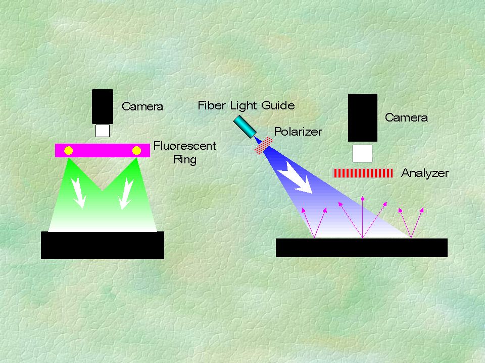
FIBER OPTICS §Single Fibers: multimode of single mode(few microns) §FIBER BUNDLES l Incoherent transfer Light l Coherent transfer Images §Cool Light, Absorbs IR & much other light §Many Shapes Available l Small for directional lighting l Rings for surround lighting l Lines, right angles, specials
 §FIBER BUNDLES l Incoherent transfer Light l Coherent transfer Images §Cool Light, Absorbs IR & much other light §Many Shapes Available l Small for directional lighting l Rings for surround lighting l Lines, right angles, specials")
26
F-mount 와 C-mount 의 비교 C-mount 와 CS-mount 의 비교 ; 플린지 백 거리의 차이

27
O : objective length I : Imaging length F b : back focal length F f : front focal length F : effective focal length H : 제 1 주요점 H” : 제 2 주요점

28
1. CCD (Charge Coupled Device) 전하 결합 소자의 일종. >> n 형 반도체 표면에 0.1 ㎛ 정도의 두께를 가진 절연층을 사 이에 두고 금속 전극이 배열 이 금속 전극의 전압을 제어 >> 반도체 표면의 전위가 낮은 부분을 좌우로 이동 >> 축적된 전하를 이에 맞추어서 순차 전송 전송 >> 시프트 레지스터나 기억 장치로 서 응용 2. CCD Camera : CCD 소자에 의한 영상재현 Camera 3. CCD Camera 의 종류 - 영상 출력 Signal 에 따라 Analog 방식 Digital(RS-422) 방식 - 영상 주사 방식에 따라 Interlace Scan Progressive Scna(Non-interlaced)
 방식 - 영상 주사 방식에 따라 Interlace Scan Progressive Scna(Non-interlaced).")
29
일반적인 CCD Camera 의 파장 감응 곡선 CCD Camera Cell Format

30
1. Interlace Scan( 비월주사 ) : 하나의 영상을 만들기 위해 두번의 수직 주사를 하는 방법 2. ProgressiveScan(Non-Interlace) : 하나의 영상을 만들기 위해 한번의 수직 주사를 하는 방법 - 1 Frame = 2 Field( Even / Odd Field) -> 완벽한 하나의 화면을 나타냄. ※ 보통의 CCD Camera 는 1 초 동안에 30 frame 의 화면을 보낼 수 있다. - 1 Field : 1 회의 수직 주사에 의해 만들어지는 거친 화면 카메라 주사 방식 주사 : 카메라가 하나의 영상을 만드는 과정
 : 하나의 영상을 만들기 위해 한번의 수직 주사를 하는 방법 - 1 Frame = 2 Field( Even / Odd Field) -> 완벽한 하나의 화면을 나타냄. ※ 보통의 CCD Camera 는 1 초 동안에 30 frame 의 화면을 보낼 수 있다. - 1 Field : 1 회의 수직 주사에 의해 만들어지는 거친 화면 카메라 주사 방식 주사 : 카메라가 하나의 영상을 만드는 과정.")
31
Line Scan Camera 의 적용 예

32
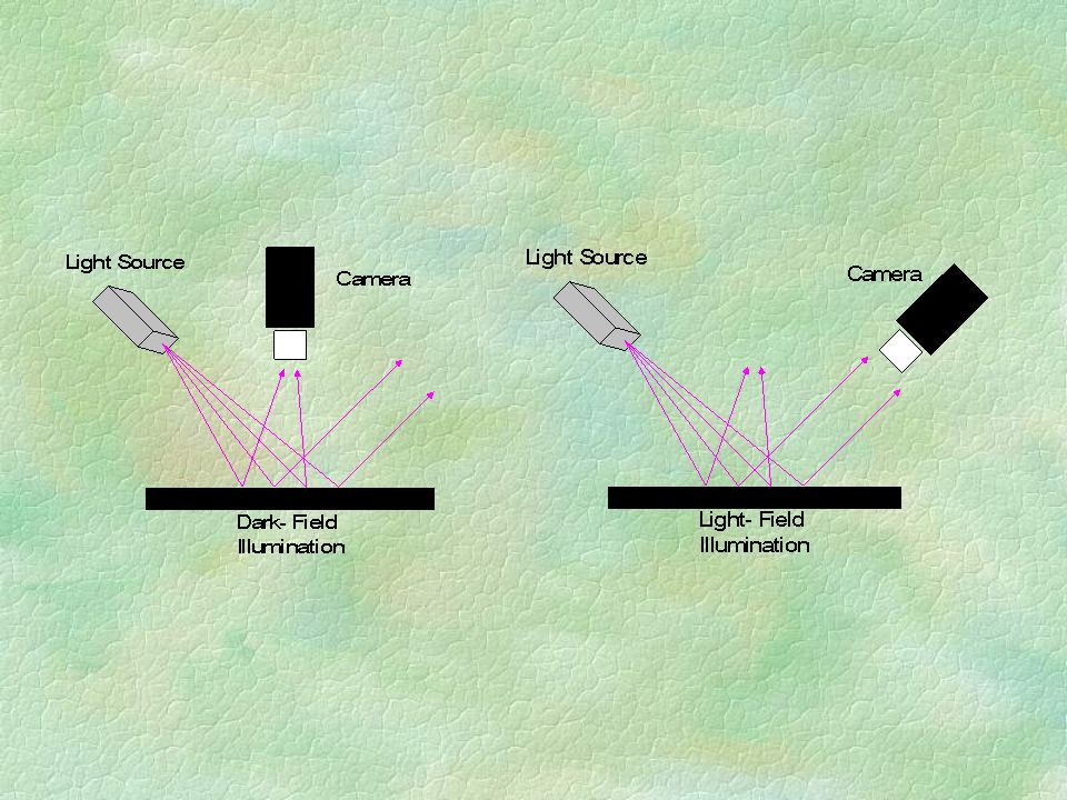
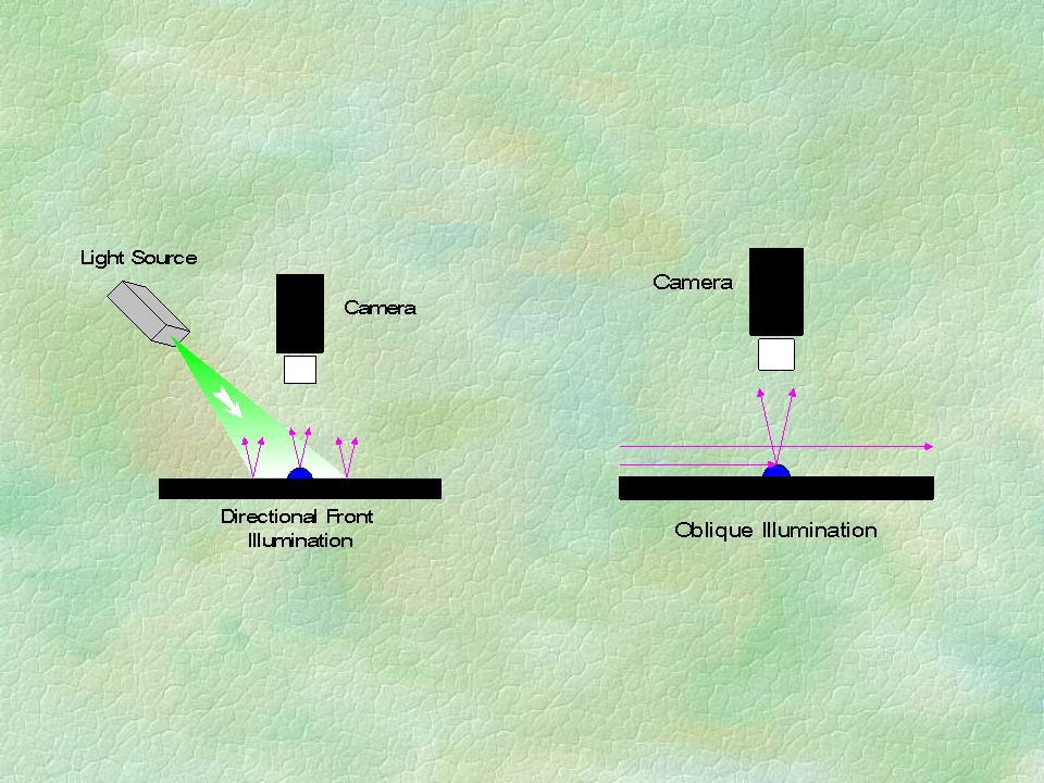
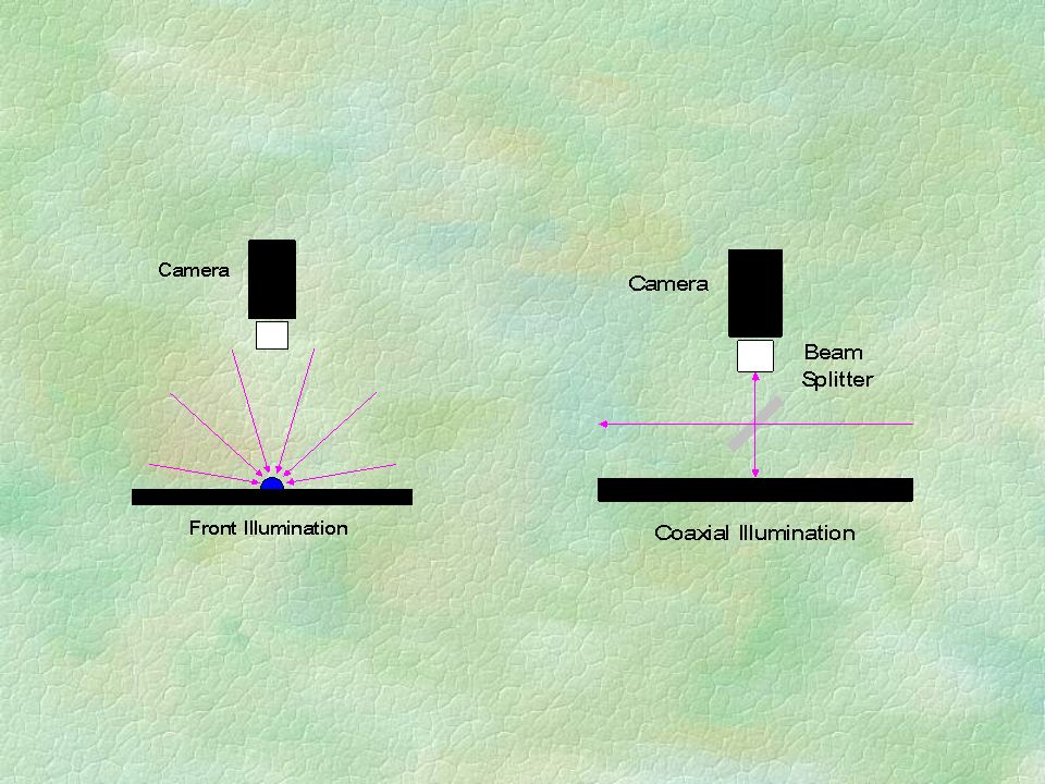
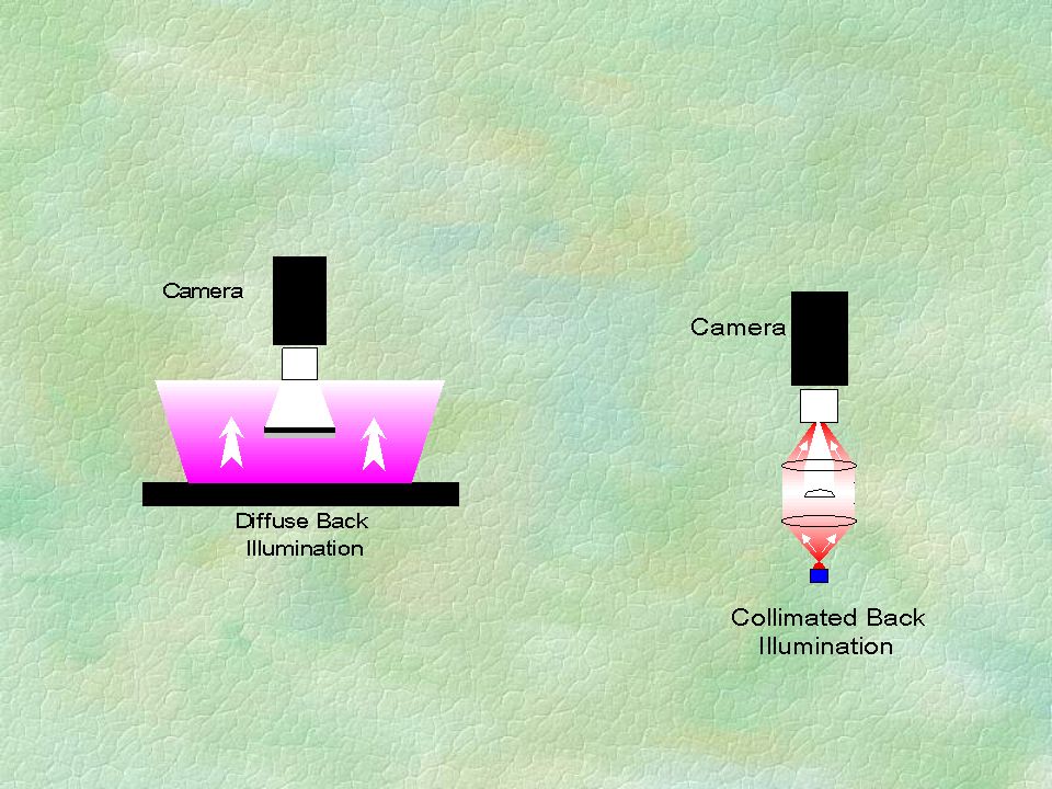
조명의 역할 검색하고자 하는 물체나 이물질이 잘 나타나도록 도와 주는 역할

37
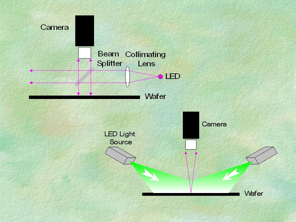
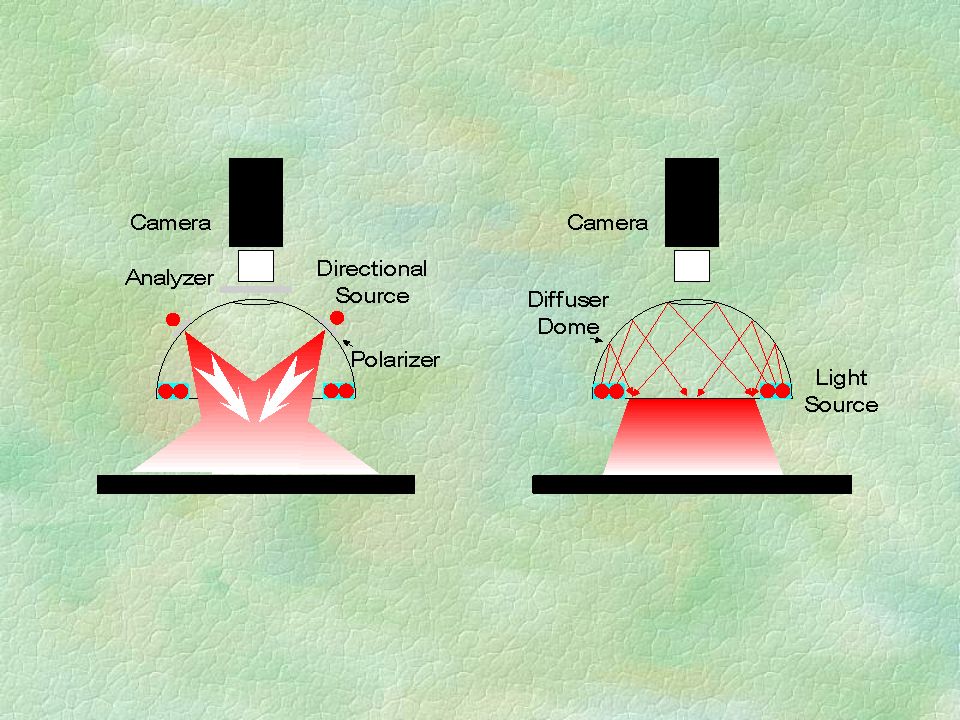
광원의 형태 및 종류 형광을 이용한 광원 LED 광원 LASER 광원 아크 광원 Fiber guide 광원 Diffuse 광원 등

41
BEAMSPLITTERS §PLATES – inexpensive, common use, high aberrations §CUBE PRISMS – protects the coating, polarizing §PELLICLE – the cleanest signal, from light to sound §ANTI-REFLECTION – ghosts and noise reduction

42
DIFFUSERS §Scatters light over a wide angle §Provides more uniform illumination §Does not maintain incident polarization §Causes some loss in intensity §Usually made of ground or opal glass

43
렌즈 성능 확인 Group Number Element Number Test Target Target 확인 Chart ※ 영상확인 할 경우 몇번째 group 에 몇번째 element 까지 보이는지 확인한다.

44
RESOLUTION §Rayliegh – two points separated by diameter >> 0.66 x wavelength/n.a. §Abbe – for coherent light >> 0.77 x wavelength/n.a. §To resolve is to discriminate, to detect is to see. §Typical high quality lens, 2 to 3 times theoretical limit §Microscope optics near theoretical limit (small F.O.V.)
.")
45
Filters 의 기능 §Removes unwanted or unused light §Attenuate given wavelengths while passing others §Available in thin films, plastic, or glass for interference, absorbing or blocking

46
§THIN FILM INTERFERENCE – high performance for a cost §INTERFERENCE filter §ABSORBING – general purpose, but not under control > Neutral Density filter, Color glass filter 등 §BLOCKING FILTERS – filter features, aberrations, views orientations and select rays (FAVOR) Filters 의 종류
 Filters 의 종류")
47
IR 이상 영역의 빛만을 이용하고자 할 경우에 사용 열선 (IR) 영역의 빛들을 제거하고자 할 경우에 사용 1) Long pass filter(Cold Mirror)2) Short pass filter(Hot Mirror) THIN FILM INTERFERENCE
 영역의 빛들을 제거하고자 할 경우에 사용 1) Long pass filter(Cold Mirror)2) Short pass filter(Hot Mirror) THIN FILM INTERFERENCE")
48
3) Band pass filter( 원하는 부분의 빛 만을 이용할 경우 사용 ) Coating 층과 물질에 따라 조절 가능 4) Dichroic Mirrors : color selective (RGB)
 Band pass filter( 원하는 부분의 빛 만을 이용할 경우 사용 ) Coating 층과 물질에 따라 조절 가능 4) Dichroic Mirrors : color selective (RGB)")
49
INTERFERENCE FILTERS §BANDPASS – highly selective wavelengths to 2nm §LONG PASS – ultra-violet blocking (fluorescence) §SHORT PASS – IR blocking, or passing green to blue §WAVELENGTH TUNING – turning green §SIDE BANDS – color glass?
 §SHORT PASS – IR blocking, or passing green to blue §WAVELENGTH TUNING – turning green §SIDE BANDS – color glass")
50
ABSORBING FILTERS §Pass colors rather than specific wavelengths §Typically color glass or gelatin §Wide selection, many commercial sources §Low cost

51
COLOR GLASS AND GELATINS §COLORS RATHER THAN WAVELENGTHS – available dyes §WHERE DOES THE LIGHT GO? – bang §NEW COLOR FOR OLD – florescent dyes §WIDE SELECTION/LOW COST – many sources, the 35mm connection

52
REFLECTION COATINGS §SILVER – old standard to 97% §GOLD – the IR standard, to 95% §ALUMINUM – the cheap standard, <90% §DIELECTRICS – selective to the best & worst

53
AR( 무반사 ) Coating - AR Coating 을 했을 경우 반사율의 비교 Uncoated at 45 deg Uncoated at 0 deg Coated at 45 deg Coated at 0 deg - AR Coating 의 원리 ※표면반사에 의해 나타나는 허상을 제거하고자 할 경우에 사용
 Coating - AR Coating 을 했을 경우 반사율의 비교 Uncoated at 45 deg Uncoated at 0 deg Coated at 45 deg Coated at 0 deg - AR Coating 의 원리 ※표면반사에 의해 나타나는 허상을 제거하고자 할 경우에 사용")
Similar presentations
![Chapter 12 Spectroscopy 1 : Rotational & Vibrational Spectra. -- Vacuum wavelength [ cm ] -- Vacuum wavenumber [ cm -1 ]](/39/10994127/big_thumb.jpg "Chapter 12 Spectroscopy 1 : Rotational & Vibrational Spectra. -- Vacuum wavelength [ cm ] -- Vacuum wavenumber [ cm -1 ]>")


프로옵틱스 회사소개서 www.prooptics.co.kr.>")


