Download presentation
Presentation is loading. Please wait.

1
의료 IT 공학과 조용석 교수 Reverse Engineering Introduction Reverse Engineering #2

2
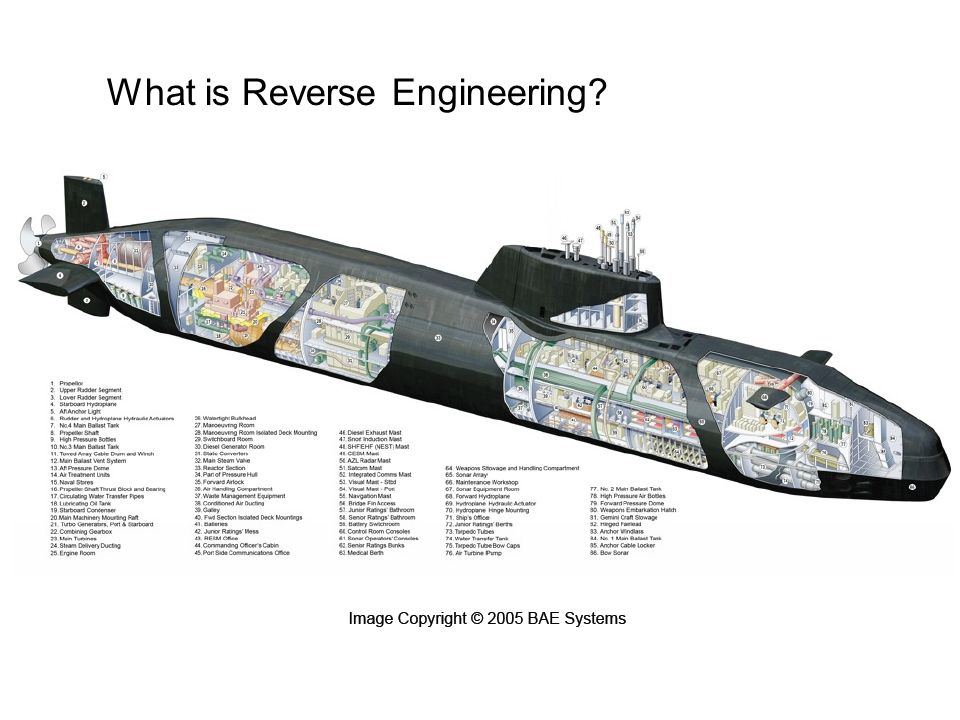
What is Reverse Engineering?

4
Reverse Code Engineering Reverse Engineering is also known as RE or RCE RE: Reverse Engineering RCE: Reverse Code Engineering RE is the process of understanding an existing product Malware analysis( 악성코드분석 ) and security research often involves RE
 and security research often involves RE")
5
Compilation Process( 컴파일 과정 ) Source CodeObject FileExecutable CompilationLinking Human readable text file Binary code with Readable symbols Binary code with no symbols Code Readability
 Source CodeObject FileExecutable CompilationLinking Human readable text file Binary code with Readable symbols Binary code with no symbols Code Readability")
6
Compilation Results

7
Uses of Reverse Engineering 악성코드분석 보안 / 약점 연구 Driver 개발 호환성 수정 Legacy application( 레거시 응용프로그램 ) 지원 Legacy application: 현재의 기술보다 이전의 언어와 플랫폼 기법으로 만들어진 애플리케이션과 데이터로 예를 들면, 윈도우 95 이상 OS 를 사용하고 있는 이때 DOS 와 윈도 3.1 응용 프로그램들 을 일컫는 말
 지원 Legacy application: 현재의 기술보다 이전의 언어와 플랫폼 기법으로 만들어진 애플리케이션과 데이터로 예를 들면, 윈도우 95 이상 OS 를 사용하고 있는 이때 DOS 와 윈도 3.1 응용 프로그램들 을 일컫는 말")
8
Ethical and Legal Aspects

9
Legal Uses Reverse Engineering

10
Illegal Activities

11
Decompilation Process( 컴파일 과정 ) Disassembly Executable DecompilationDisassembly Reverse Engineer Readable Code Binary code with no symbols Code Readability Source Code Human Readable Code
 Disassembly Executable DecompilationDisassembly Reverse Engineer Readable Code Binary code with no symbols Code Readability Source Code Human Readable Code")
12
Disassembly Results

13
Required Skills 일반적인 컴퓨터구조 지식 관련 프로세서에 대한 어셈블리어 프로그래밍 운영체제 (Operating Systems) 파일형태 (File Format) 자료수집 능력
 파일형태 (File Format) 자료수집 능력")
14
사용되고 있는 도구들 (Tools) hex editor/viewer Disassembler Search Engine Debugger Script language
 hex editor/viewer Disassembler Search Engine Debugger Script language")
15
Getting Started Master your tools Identify the target binary format Identify the target processor Identify the target operating system …dig in and find out as much as you can….

16
Reverse engineering primary output 1.block diagram 2.schematic diagram 3.circuit board layout 4.Flowchart 5.operations manual

17
1.block diagram 의 정의 A diagram in which the essential units of any system are drawn in the form of rectangles or blocks and their relation to each other is indicated by appropriate connecting lines. A diagram of a system, in which the principal parts or functions are represented by blocks connected by lines, that show the relationships of the blocks. They are heavily used in the engineering world in hardware design, electronic design, software design, and process flow diagrams.diagramsystemhardware design electronic designsoftware designprocess flow diagrams Black box Data flow diagram

18
block diagram Symbol

19
1.block diagram

20
1.block diagram1

21
1.block diagram(Drawing)
")
22
2.schematic diagram A schematic diagram represents the elements of a system using abstract, graphic symbols rather than realistic picturessystemsymbols A drawing showing all significantcomponents, parts, or tasks (and their interconnections) of a circuit, device, flow, process, or project by means of standardsymbols. Schematic diagrams for a project may also be used for preparing preliminary cost estimates.drawingsignificantcomponentspartstaskscircuitdeviceflowprocessprojectmeansstandardsymbolscost estimates

23
2.schematic diagram

24
2.schematic diagram(Drawing)
")
25
2.schematic diagram(Drawing1)
")
26
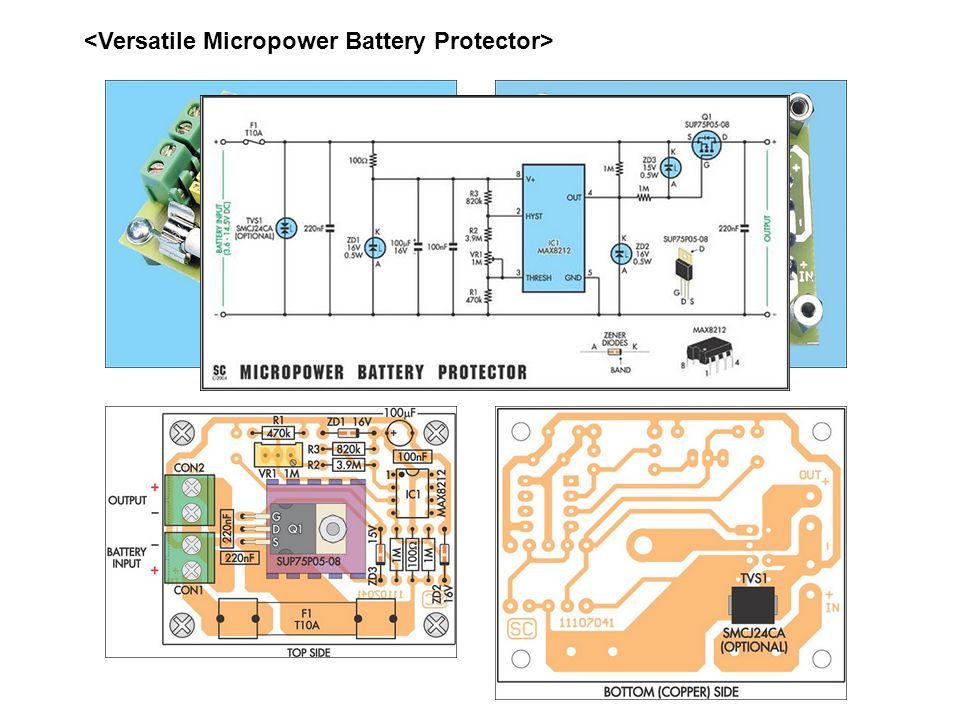
3.circuit board layout

28
3.circuit board layout(Drawing)
")
29
4.Flowchart A flowchart is a type of diagram that represents an algorithm or process, showing the steps as boxes of various kinds, and their order by connecting these with arrows.diagramalgorithm process 간단한 Flowchart 의 예 ) 1.http://www.rff.com/flowchart_samples.htmhttp://www.rff.com/flowchart_samples.htm 2.http://www.edrawsoft.com/flowchart-examples.php
")
30
4.Flowchart

31
4.Flowchart(Drawing)
")
32
5.operations manual

Similar presentations


>")
 01/ Network 생활코딩 – 웹 서비스 만들기 (4 주 ) Wowhacker 웹 게임 (4 주 ) 02/ Web 뇌를 자극하는 윈도우 시스템 프로그래밍 (4 주 ) 리버싱.>")
![이력서 작성법 서강대학교 전자공학과. 이력서 이력서란 ? ◦ 이력서 ( 履歷書 ) a rsum 《미》 ;a personal history[statement];a curriculum vitae 《라》 ;a record of one’s life ◦ 이력 [ 履歷 ] [ 명사.](/40/11110402/big_thumb.jpg "이력서 작성법 서강대학교 전자공학과. 이력서 이력서란 ? ◦ 이력서 ( 履歷書 ) a rsum 《미》 ;a personal history[statement];a curriculum vitae 《라》 ;a record of one’s life ◦ 이력 [ 履歷 ] [ 명사.>")
, 고광춘, 유기민, 김대진, 이재호 발표 일자:>")


>")
>")


![과목 홈페이지 전산학개론 이메일 숙제를 제출할 경우, 메일 제목은 반드시 ‘[전산학개론]’으로 시작.](/90/14487693/big_thumb.jpg "과목 홈페이지 전산학개론 이메일 숙제를 제출할 경우, 메일 제목은 반드시 ‘[전산학개론]’으로 시작.>")
