Download presentation
Presentation is loading. Please wait.

1
Layer-2 Switching - 스위치는 multiport bridge( bridges with more ports)라 할 수 있다. 브리지가 소프트웨어 베이스라 한다면 스위치는 하드웨어 베이스로 지연시간이 적다.(Low Latency) Filtering Decision을 위해 ASIC(Application Specific Integrated Circuits) 칩을 사용한다. 성능대비 가격이 저렴하다.(Low cost) 브리지는 최대 16개의 포트를 갖을 수 있으나 스위치는 수백개의 포트를 갖을 수 있다. 브리지는 하나의 Spanning Tree만을 갖을 수 있으나 스위치는 여러 개의 Spanning Tree를 갖을 수 있다.
 Filtering Decision을 위해 ASIC(Application Specific Integrated Circuits) 칩을 사용한다. 성능대비 가격이 저렴하다.(Low cost) 브리지는 최대 16개의 포트를 갖을 수 있으나 스위치는 수백개의 포트를 갖을 수 있다. 브리지는 하나의 Spanning Tree만을 갖을 수 있으나 스위치는 여러 개의 Spanning Tree를 갖을 수 있다.")
2
Spanning Tree Protocol( IEEE 802.1 Standard)
STP는 지속적으로 네트워크를 모니터링하여 모든 링크를 발견하고, 중복된 링크가 존재하는지를 검색하여 중복된 링크가 있으면 하나의 링크를 Blocking Mode로 만들어 Loop을 방지한다. SPT를 지원하는 브리지 및 스위치를 사용하여 중복된 링크를 구성하고, 평상시에는 하나의 경로를 사용하다가, 그 경로에 문제가 생기는 경우 다음 경로를 사용하도록 하여 Link Redundancy를 확보할 수 있다. 스위치간에 BPDU(Bridge Packet Data Unit) 프레임을 교환하여 중복된 링크의 Port의 Forwarding 및 Blocking Mode를 결정하는데, 네트워크 상의 새로운 스위치를 연결하거나, Link Fail 등 토폴로지에 변경이 발생하는 경우, STP는 경로를 재계산하여 Port의 모드를 변경한다. 이를 Convergence라 하며 Blocking Mode에서 Forwarding Mode로 바뀌는 동안에는 데이터 전송이 중단되며 Default STP Timer로 설정된 50초의 시간이 소요된다.
 프레임을 교환하여 중복된 링크의 Port의 Forwarding 및 Blocking Mode를 결정하는데, 네트워크 상의 새로운 스위치를 연결하거나, Link Fail 등 토폴로지에 변경이 발생하는 경우, STP는 경로를 재계산하여 Port의 모드를 변경한다. 이를 Convergence라 하며 Blocking Mode에서 Forwarding Mode로 바뀌는 동안에는 데이터 전송이 중단되며 Default STP Timer로 설정된 50초의 시간이 소요된다.")
3
Loop 발생시 Broadcast Storm
Server A Sw Sw Sw Node A Node B

4
Spanning Tree Protocol
MAC 0c00c Default priority 32768 Root Bridge Sw Sw Sw MAC 0c00c Default priority 32768 MAC 0c00c Default priority 32768 Node A Node B Forwarding/Block Mode 결정 요소 1.Default Priority 2.MAC Address 3.Bandwidth

5
Selecting the Root Bridge
STP 프로토콜을 지원하는 브리지 및 스위치들은 Bridge ID정보를 포함하는 BPDU(Bridge Protocol Data Units)라는 멀티캐스트 프레임을 교환한다. BPDU는 디폴트로 2초 간격으로 보내어 지며 특정 멀티캐스트 어드레스를 Destination Address로 하므로 Broadcast Domain에 걸쳐 전달된다 . - Bridge ID는 Bridge Priority(특별히 설정하지 않으면 32,768 값이 Default 값이다.)와 MAC Address로 구성되며 네트워크 상의 Root Bridge를 결정하는데 사용된다. 스위치들의 Bridge Priority가 동일한 경우 MAC Address가 낮은 스위치가 Root Bridge가 결정된다.루트브리지의 모든 포트는 Designated Port라 하여 Forwarding Mode로 설정된다. Selecting the Root Port 루트브리지가 아닌 각 스위치의 포트에서 루트 브리지에 이르는 Cost가 적은 포트가 Root Port가 된다. Cost는 대역폭에 의해서 결정된다.Root Port는 Forwarding State가 된다. Selecting the Designated Port 루트 브리지가 아닌 각 스위치에서 루트포트가 아닌 포트끼리 루트 브리지에 이르는 Cost를 비교하여 적은 Cost를 갖는 포트가 Designated Port가 된다. Designated Port는 Forwarding State가 된다. Blocking Mode의 Port도 BPDU를 Listening 한다. 55
라는 멀티캐스트 프레임을 교환한다. BPDU는 디폴트로 2초 간격으로 보내어 지며 특정 멀티캐스트 어드레스를 Destination Address로 하므로 Broadcast Domain에 걸쳐 전달된다 . - Bridge ID는 Bridge Priority(특별히 설정하지 않으면 32,768 값이 Default 값이다.)와 MAC Address로 구성되며 네트워크 상의 Root Bridge를 결정하는데 사용된다. 스위치들의 Bridge Priority가 동일한 경우 MAC Address가 낮은 스위치가 Root Bridge가 결정된다.루트브리지의 모든 포트는 Designated Port라 하여 Forwarding Mode로 설정된다. Selecting the Root Port. 루트브리지가 아닌 각 스위치의 포트에서 루트 브리지에 이르는 Cost가 적은 포트가 Root Port가 된다. Cost는 대역폭에 의해서 결정된다.Root Port는 Forwarding State가 된다. Selecting the Designated Port. 루트 브리지가 아닌 각 스위치에서 루트포트가 아닌 포트끼리 루트 브리지에 이르는 Cost를 비교하여 적은 Cost를 갖는 포트가 Designated Port가 된다. Designated Port는 Forwarding State가 된다. Blocking Mode의 Port도 BPDU를 Listening 한다. 55.")
6
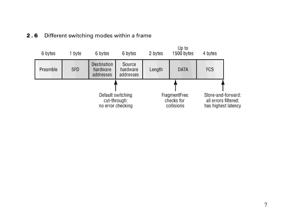
LAN Switch Types Store and forward 데이타프레임 전부가 스위치의 버퍼에 담겨져 Destination Address는 물론이고 CRC 체크 및 Gigants,Runts 체크 등을 한 후 해당포트로 Forwarding 시키는 방식이다. Cut-through Destination hardware Address(프레임의 앞부분 6Byte)만을 읽어 Forwarding한다. FragmentFree (modified cut-through) 프레임의 64 바이트만을 읽어 에러를 처리하고 목적지 포트로 Forwarding하는 방식이다.64 바이트의 정보에서 대부분의 에러프레임을 판별할 수 있다.
만을 읽어 Forwarding한다. FragmentFree (modified cut-through) 프레임의 64 바이트만을 읽어 에러를 처리하고 목적지 포트로 Forwarding하는 방식이다.64 바이트의 정보에서 대부분의 에러프레임을 판별할 수 있다.")
8
Layer3 Switch & VLAN(Virtual LAN)
Router를 사용하지 않고 Layer3를 지원하는 Layer3 Switch를 사용하여 여러 개의 상이한 서브넷을 만들 수 있다. Layer 2 Switch의 경우는 각각의 Port별로 상이한 Collision Domain을 생성하나 브로드캐스트 Packet은 전 포트에 전달되며 각 포트에서 다른 포트를 통해 송수신되는 패킷을 잡을 수 있어 Security 영역을 분할 할 수 없다. VLAN의 효용 - 브로드캐스트 제어(Broadcast Control)할 수 있다. - 보안(Security)을 제공한다. - 네트워크의 유연성 및 확장성(Flexibility and Scalability)을 제공한다.
할 수 있다. - 보안(Security)을 제공한다. - 네트워크의 유연성 및 확장성(Flexibility and Scalability)을 제공한다.")
9
Ethernet switching. VLAN Overview

10
Typical VLAN topology.

11
VLAN 구성 Static VLAN ( Port Base VLAN ) - 스위치 포트 별로 VLAN 소속을 설정한다. 설치 및 모니터링이 용이하다. Dynamic VLAN ( MAC Address Base VLAN) VLAN Management Policy Server (VMPS)를 사용해야 한다. VMPS는 MAC address의 VLAN 에 대한 매핑 데이타베이스 서버로 Catalyst 5,000 스위치나 별도의 서버를 사용한다.
를 사용해야 한다. VMPS는 MAC address의 VLAN 에 대한 매핑 데이타베이스 서버로 Catalyst 5,000 스위치나 별도의 서버를 사용한다.")
12
VLAN은 다수의 스위치에 걸쳐 구성될 수 있다.
VLAN Between Switches VLAN은 다수의 스위치에 걸쳐 구성될 수 있다. 여러 스위치에 걸친 VLAN을 구성하기위해 스위치들은 Trunk link로 연결되어야 한다. Trunked link는 Fast Ethernet 또는 Gigabit Ethernet 포트를 통해서만 연결될 수 있다. Full Duplex 및 Half Duplex 설정 모두 가능하며, 스위치간에 하나 또는 그 이상의 Trunk Link도 가능하다. Trunked Link는 개의 VLAN을 연결할 수 있다. ISL(Inter Switch Link) Protocol 여러 개의 스위치에 걸쳐 VLAN을 구성할 수 있는데 이러한 스위치간 VLAN을 지원하는 프로토콜이다. ISL은 시스코 장비간에만 사용가능하므로 다른 Vendor의 장비와 연결하기 위해서는 802.1q 프로토콜을 사용해야 한다. ISL은 원래의 프레임을 변경시키지 않고 26 Byte의 ISL Header와 4 Byte의 FCS를 추가하여 트렁크 링크를 통과시킨다.(ISL Tagging이라 한다.) 포트에 연결된 노드(허브 또는 PC)에서 만들어진 프레임이 스위치 포트로 들어가면서 VLAN Tag 가 추가되고, 스위치간의 ISL이 ISL Header가 추가된 프레임을 스위치간에 전달하며, 프레임이 스위치 포트에서 스위치 포트에 연결된 노드로 이동하면서 VLAN Tag가 제거된다. ISL Header에는 VLAN 필드가 있어 VLAN정보가 스위치간에 전달된다.
 Protocol. 여러 개의 스위치에 걸쳐 VLAN을 구성할 수 있는데 이러한 스위치간 VLAN을 지원하는 프로토콜이다. ISL은 시스코 장비간에만 사용가능하므로 다른 Vendor의 장비와 연결하기 위해서는 802.1q 프로토콜을 사용해야 한다. ISL은 원래의 프레임을 변경시키지 않고 26 Byte의 ISL Header와 4 Byte의 FCS를 추가하여 트렁크 링크를 통과시킨다.(ISL Tagging이라 한다.) 포트에 연결된 노드(허브 또는 PC)에서 만들어진 프레임이 스위치 포트로 들어가면서 VLAN Tag 가 추가되고, 스위치간의 ISL이 ISL Header가 추가된 프레임을 스위치간에 전달하며, 프레임이 스위치 포트에서 스위치 포트에 연결된 노드로 이동하면서 VLAN Tag가 제거된다. ISL Header에는 VLAN 필드가 있어 VLAN정보가 스위치간에 전달된다.")
13
Trunking ISL Configuration ISL Tagging VLAN Tag Added
VLAN Tag Stripped ISL Configuration

14
여러 개의 VLAN에 연결된 서버 서버에 ISL 프로토콜을 지원하는 NIC(Fast Ethernet Card)를 장착하여 서버를 여러 개의 VLAN에 연결할 수 있다. (스위치 포트와 ISL NIC를 Trunking 한다.) 이 경우 VLAN을 통해 서브넷으로 노드들을 분할하여 Security를 제공하면서 모든 서브넷에서 서버에 Access할 수 있다. Routing between VLANs (Cisco의 경우) series router : ISL routing을 지원하는 Fast Ethernet Port와 Switch Port를 Trunk로 연결한다. series switch : Route switch module (RSM)을 스위치에 장착하면 1005개 까지의 VLAN을 연결할 수 있다.
를 장착하여 서버를 여러 개의 VLAN에 연결할 수 있다. (스위치 포트와 ISL NIC를 Trunking 한다.) 이 경우 VLAN을 통해 서브넷으로 노드들을 분할하여 Security를 제공하면서 모든 서브넷에서 서버에 Access할 수 있다. Routing between VLANs (Cisco의 경우) series router : ISL routing을 지원하는 Fast Ethernet Port와 Switch Port를 Trunk로 연결한다 series switch : Route switch module (RSM)을 스위치에 장착하면 1005개 까지의 VLAN을 연결할 수 있다.")
15
VTP (Virtual Trunking Protocol)
스위치간의 Trunk Link를 통하여 VLAN 설정 정보를 하나 또는 그 이상의 스위치에서 통합적으로 관리하기 위한 프로토콜로 VLAN이 2개 이상인 경우에 사용될 수 있다. VTP benefits - Consistent VLAN configuration across all switches in the network - Accurate tracking and monitoring of VLANs Dynamic reporting of added VLANs to all switches

16
VTP modes Server - default for all Catalyst switches. at least one server in VTP domain Can create, add, change or delete VLANs in a VTP domain. Any change made to a switch in server mode is advertised to the entire VTP domain. Client Can Receives information from VTP servers and send and receives updates Cannot make any changes. No ports on a client switch can beadded to a new VLAN before the VTP server notifies the client switch of the new VLAN. Transparent not participate in the VTP domain but will still for-ward VTP advertisements through the configured trunk links. VTP trans-parent switches can add and delete VLANs as the switch keeps its own Local database and does not share it with other switches.

17
VTP Advertisement and Update

18
VTP Pruning VLAN 5에 소속되는 포트가 없는 스위치에는 VLAN 5에 보내지는 트래픽을 보내지 않도록 하여 트래픽을 조절한다. VLAN Tag가 VLAN5인 패킷은 넘기지 않는다. VTP pruning은 기본적으로 모든 스위치에 Disable이다. VLAN 2–1005 가 Pruning이 가능하다. VLAN 1 은 Pruning 될 수 없다.

19
Flooding Traffic without VTP Pruning
Port 1 on Switch 1 and port 2 on Switch 4 are assigned to the Red VLAN. A broadcast is sent from the host connected to Switch 1. Switch 1 floods the broadcast and every switch in the network receives it, even though Switches 3, 5, and 6 have no ports in the Red VLAN.

20
Flooding Traffic with VTP Pruning
The broadcast traffic from Switch 1 is not forwarded to Switches 3, 5, and 6 because traffic for the Red VLAN has been pruned on the links indicated (port 5 on Switch 2 and port 4 on Switch 4).
.")
21
VLAN Configuration VLAN1은 Factory Default VLAN이다. CDP, VTP Advertisement는 VLAN1을 통해서 보내진다. 각각의 VLAN은 별개의 서브넷으로 구성되어야 하며, Switch IP Address는 VLAN1에 소속되어야 한다. VLAN은 개까지 지원될 수 있으며, Maximum은 스위치별로 상이하다. Catalyst Switch 1900의 경우 64개의 VLAN을 지원한다. VTP를 사용하는 경우, VLAN을 생성,추가,삭제하기 위해서는 스위치가 Server 모드 또는 Transparent 모드여야 한다. Client 모드에서는 불가하다. Transparent 모드인 경우는 그 스위치 에만 국한된 VLAN이 생성된다. VLAN Membership은 각각의 스위치에서 포트별로 수동 할당해야 한다. VTP Pruning을 VTP Server에서 하게 되면 전체 도메인에 적용된다. VTP Domain에 스위치를 추가하는 경우 Client Mode로 설정하여 추가해야 한다. Server 모드인 경우 추가하는 스위치에 이미 설정된 VLAN 정보가 전파된다. delete vtp 명령으로 vtp 설정을 제거한 후에 추가하는 것도 한 방법이다. VTP Domain Password는 모든 스위치에서 동일해야 한다.

22
Configuring the Catalyst 1900 Switch
Types of operating systems IOS-based CLI similar to Cisco routers. Catalyst 1900, 2820, and 2900 switches can be can be set with a menu system as well. Set-based - older, set-based CLI configuration com-mands. 2926, 1948G, 4000, 5000, and 6000 series. Three Configuration Options - CLI Web-based method using the Visual Switch Manager (VSM). - Menu system
. - Menu system.")
23
Catalyst 1900 switch System Green light : switch is operational. Amber light : system malfunction has occurred RPS ( redundant power supply) light : RPS is detected in the switch.
 light : RPS is detected in the switch.")
24
UTL : bandwidth of the switch.
Light 1 through 4 : bandwidth utilization between 0.1 and1.5Mbps lights 5 through 8 : between 1.5 and 20Mbps lights 9 through 12 : between 20 and 120Mbps. FDUP : full duplex ports

25
Setting the Passwords - Four characters - eight. Not case sensitive. User mode password : level number 1. Enable mode password : level mode 15. (config)#enable password level 1 password (config)#enable password level 15 wordpass Setting the Hostname #config t Enter configuration commands, one per line. End with CNTL/Z (config)#hostname C1900_1
#enable password level 1 password. (config)#enable password level 15 wordpass. Setting the Hostname. #config t. Enter configuration commands, one per line. End with CNTL/Z. (config)#hostname C1900_1.")
26
Setting IP Information
To manage the switch via Telnet or other man-agement software Toconfigure the switch with different VLANs and other network functions. C1900_1#config term Enter configuration commands, one per line. End with CNTL/Z C1900_1(config)#ip address C1900_1(config)#ip de C1900_1(config)#ip default-gateway C1900_1#sh ip IP Address: Subnet Mask: Default Gateway: Management VLAN: 1 Domain name: Name server 1: Name server 2: HTTP server : Enabled HTTP port : 80 RIP : Enabled
#ip address C1900_1(config)#ip de. C1900_1(config)#ip default-gateway C1900_1#sh ip. IP Address: Subnet Mask: Default Gateway: Management VLAN: 1. Domain name: Name server 1: Name server 2: HTTP server : Enabled. HTTP port : 80. RIP : Enabled.")
27
Configuring Switch Interfaces ( Slot / Port)
C1900_1#config t Enter configuration commands, one per line. End with CNTL/Z C1900_1(config)#int ethernet 0/1 C1900_1(config-if)#? Interface configuration commands: cdp Cdp interface subcommands description Interface specific description duplex Configure duplex operation exit Exit from interface configuration mode help Description of the interactive help system no Negate a command or set its defaults port Perform switch port configuration shutdown Shutdown the selected interface spantree Spanning tree subsystem vlan-membership VLAN membership configuration
#int ethernet 0/1. C1900_1(config-if)# Interface configuration commands: cdp Cdp interface subcommands. description Interface specific description. duplex Configure duplex operation. exit Exit from interface configuration mode. help Description of the interactive help system. no Negate a command or set its defaults. port Perform switch port configuration. shutdown Shutdown the selected interface. spantree Spanning tree subsystem. vlan-membership VLAN membership configuration.")
28
AUI Port C1900_1#config t Enter configuration commands, one per line. End with CNTL/Z C1900_1(config)#int e 0/25 Fast Ethernet Port C1900_1(config)#int C1900_1(config)#interface f C1900_1(config)#interface fastEthernet 0/26 C1900_1(config)#interface fastEthernet 0/27
#int. C1900_1(config)#interface f. C1900_1(config)#interface fastEthernet 0/26. C1900_1(config)#interface fastEthernet 0/27.")
29
C1900_1#sh int e0/1 Ethernet 0/1 is Enabled Hardware is Built-in 10Base-T Address is E3.B281 MTU 1500 bytes, BW Kbits 802.1d STP State: Forwarding Forward Transitions: 1 Port monitoring: Disabled Unknown unicast flooding: Enabled Unregistered multicast flooding: Enabled Description: Duplex setting: Half duplex Back pressure: Disabled

30
Setting Descriptions - Describe each interface. - More than one word - Can’t use spaces. Can use the underscore C1900_1#config t Enter configuration commands, one per line. End with CNTL/Z C1900_1(config)#int e 0/1 C1900_1(config-if)#description Sales_VLAN
#int e 0/1. C1900_1(config-if)#description Sales_VLAN.")
31
Configuring the Port Duplex

32
C1900_1#config t Enter configuration commands, one per line. End with CNTL/Z C1900_1(config)#int e 0/1 C1900_1(config-if)#duplex ? auto Enable auto duplex configuration full Force full duplex operation full-flow-control Force full duplex with flow control half Force half duplex operation 1900_1#config t C1900_1(config)#int f0/26 C1900_1(config-if)#duplex half
#duplex auto Enable auto duplex configuration. full Force full duplex operation. full-flow-control Force full duplex with flow control. half Force half duplex operation. 1900_1#config t. C1900_1(config)#int f0/26. C1900_1(config-if)#duplex half.")
33
Verifying IP Connectivity
Catalist 1900 스위치에서 Ping을 사용할 수 있다. C1900_1#ping Sending 5, 100-byte ICMP Echos to , time out is 2 seconds: !!!!! Success rate is 100 percent (5/5), round-trip min/avg/max 0/0/0/ ms - Catalist 1900 스위치에서 telnet을 사용할 수 없다. 다른 노드에서 Catalist Switch로 Telnet은 가능하다. C1900_1#telnet ^ % Invalid input detected at '^' marker.
, round-trip min/avg/max 0/0/0/ ms. - Catalist 1900 스위치에서 telnet을 사용할 수 없다. 다른 노드에서 Catalist Switch로. Telnet은 가능하다. C1900_1#telnet ^ % Invalid input detected at ^ marker.")
34
Erasing the Switch Configuration
C1900_1#delete nvram This command resets the switch with factory defaults. All system parameters will revert to their default factory settings. All static and dynamic addresses will be removed. Reset system with factory defaults, [Y]es or [N]o?

35
Managing the MAC Address Table
- Dynamic, permanent, and static addresses. - MAC table is created by hosts sending a frame and by the switch learning the source MAC address and from which segment and port it was received. If a device is removed, or if it is not connected to the switch for a period of time, the switch will age out the entry. The Catalyst 1900 switch can store up to 1024 MAC addresses in the fil-ter table. If the MAC filter table gets full, the switch will flood all new addresses until one of the existing entries gets aged out. C1900_1#sh mac-address-table Number of permanent addresses : 0 Number of restricted static addresses : 0 Number of dynamic addresses : 1 Address Dest Interface Type Source Interface List E.3EC4 Ethernet 0/ Dynamic All

36
Clearing Mac Address C1900_1#clear mac-address-table C1900_1#sh mac-address-table Number of permanent addresses : 0 Number of restricted static addresses : 0 Number of dynamic addresses : 0 Address Dest Interface Type Source Interface List C1900_1#

37
Setting Permanent MAC Address Entries
C1900_1#config t Enter configuration commands, one per line. End with CNTL/Z C1900_1(config)#mac-address-table permanent e.3ec4 e0/1 C1900_1(config)#mac-address-table permanent e.3ec4 e0/4 e.3ec4 Mac Address를 가진 디바이스는 e0/1과 e0/4에서만 정상적으로 작동한다. C1900_1#sh mac-address-table Number of permanent addresses : 1 Number of restricted static addresses : 0 Number of dynamic addresses : 1 Address Dest Interface Type Source Interface List E.3EC4 Ethernet 0/ Permanent All E.3EC4 Ethernet 0/ Permanent All F2.A73B Ethernet 0/ Dynamic All
#mac-address-table permanent e.3ec4 e0/1. C1900_1(config)#mac-address-table permanent e.3ec4 e0/ e.3ec4 Mac Address를 가진 디바이스는 e0/1과 e0/4에서만 정상적으로 작동한다. C1900_1#sh mac-address-table. Number of permanent addresses : 1. Number of restricted static addresses : 0. Number of dynamic addresses : 1. Address Dest Interface Type Source Interface List E.3EC4 Ethernet 0/1 Permanent All E.3EC4 Ethernet 0/4 Permanent All F2.A73B Ethernet 0/10 Dynamic All.")
38
Setting Static MAC Address Entries
C1900_1#config t Enter configuration commands, one per line. End with CNTL/Z C1900_1(config)#mac-address-table restricted static e.3ec4 e0/2 e0/5 C1900_1(config)# C1900_1#sh mac-address-table Number of permanent addresses : 0 Number of restricted static addresses : 1 Number of dynamic addresses : 1 Address Dest Interface Type Source Interface List E.3EC4 Ethernet 0/ Static Et0/5 F2.A73B Ethernet 0/ Dynamic All e.3ec4 Mac Address를 가진 디바이스는 e0/2에서만 정상적으로 작동하며 E0/5에서만 Access할 수 있다.
#mac-address-table restricted static e.3ec4 e0/2 e0/5. C1900_1(config)# C1900_1#sh mac-address-table. Number of permanent addresses : 0. Number of restricted static addresses : 1. Number of dynamic addresses : 1. Address Dest Interface Type Source Interface List E.3EC4 Ethernet 0/2 Static Et0/ F2.A73B Ethernet 0/1 Dynamic All e.3ec4 Mac Address를 가진 디바이스는 e0/2에서만 정상적으로 작동하며. E0/5에서만 Access할 수 있다.")
39
Configuring Port Security
C1900_1#config t Enter configuration commands, one per line. End with CNTL/Z C1900_1(config)#int e0/3 C1900_1(config-if)#port ? block Forwarding of unknown uni/multi cast addresses secure Configure an interface to be a secure port C1900_1(config-if)#port secure ? max-mac-count Maximum number of addresses allowed on the port <cr> C1900_1(config-if)#port secure max-mac-count ? <1-132> Maximum mac address count for this secure port C1900_1(config-if)#port secure max-mac-count 1
#int e0/3. C1900_1(config-if)#port block Forwarding of unknown uni/multi cast addresses. secure Configure an interface to be a secure port. C1900_1(config-if)#port secure max-mac-count Maximum number of addresses allowed on the port. <cr> C1900_1(config-if)#port secure max-mac-count <1-132> Maximum mac address count for this secure port. C1900_1(config-if)#port secure max-mac-count 1.")
40
Using the Show Version Command
C1900_1#sh ver Cisco Catalyst 1900/2820 Enterprise Edition Software Version V Copyright (c) Cisco Systems, Inc C1900_1 uptime is 0day(s) 02hour(s) 22minute(s) 22second(s) cisco Catalyst 1900 (486sxl) processor with 2048K/1024K bytes of memory Hardware board revision is 5 Upgrade Status: No upgrade currently in progress. Config File Status: No configuration upload/download is in progress 27 Fixed Ethernet/IEEE interface(s) Base Ethernet Address: E3-B2-80
 Cisco Systems, Inc C1900_1 uptime is 0day(s) 02hour(s) 22minute(s) 22second(s) cisco Catalyst 1900 (486sxl) processor with 2048K/1024K bytes of memory. Hardware board revision is 5. Upgrade Status: No upgrade currently in progress. Config File Status: No configuration upload/download is in progress. 27 Fixed Ethernet/IEEE interface(s) Base Ethernet Address: E3-B2-80.")
41
Changing the LAN Switch Type
C1900_1#sh port system Switching mode: FragmentFree Use of store and forward for multicast: Disabled C1900_1#config t Enter configuration commands, one per line. End with CNTL/Z C1900_1(config)#switching-mode ? fragment-free Fragment Free mode store-and-forward Store-and-Forward mode sC1900_1(config)#switching-mode store-and-forward Switching mode: Store-and-Forward
#switching-mode fragment-free Fragment Free mode. store-and-forward Store-and-Forward mode. sC1900_1(config)#switching-mode store-and-forward. Switching mode: Store-and-Forward.")
42
Configuring VLANs - can create up to 64 VLANs on a 1900 switch. C1900_1#config t Enter configuration commands, one per line. End with CNTL/Z C1900_1(config)#vlan 2 name sales C1900_1#sh vlan VLAN Name Status Ports 1 default Enabled , AUI, A, B 2 sales Enabled 1002 fddi-default Suspended 1003 token-ring-defau Suspended 1004 fddinet-default Suspended 1005 trnet-default Suspended
#vlan 2 name sales. C1900_1#sh vlan. VLAN Name Status Ports default Enabled 1-24, AUI, A, B. 2 sales Enabled fddi-default Suspended token-ring-defau Suspended fddinet-default Suspended trnet-default Suspended.")
43
Assigning Switch Ports to VLANs
C1900_1#config t Enter configuration commands, one per line. End with CNTL/Z C1900_1(config)#int e0/20 C1900_1(config-if)#vlan-membership ? dynamic Set VLAN membership type as dynamic static Set VLAN membership type as static C1900_1(config-if)#vlan-membership s C1900_1(config-if)#vlan-membership static ? <1-1005> ISL VLAN index C1900_1(config-if)#vlan-membership static 2 C1900_1#sh vlan VLAN Name Status Ports 1 default Enabled , 21-24, AUI, A, B 2 sales Enabled 1002 fddi-default Suspended 1003 token-ring-defau Suspended 1004 fddinet-default Suspended 1005 trnet-default Suspended
#int e0/20. C1900_1(config-if)#vlan-membership dynamic Set VLAN membership type as dynamic. static Set VLAN membership type as static. C1900_1(config-if)#vlan-membership s. C1900_1(config-if)#vlan-membership static <1-1005> ISL VLAN index. C1900_1(config-if)#vlan-membership static 2. C1900_1#sh vlan. VLAN Name Status Ports default Enabled 1-19, 21-24, AUI, A, B. 2 sales Enabled fddi-default Suspended token-ring-defau Suspended fddinet-default Suspended trnet-default Suspended.")
44
C1900_1#sh vlan 2 VLAN Name Status Ports 2 sales Enabled 20 VLAN Type SAID MTU Parent RingNo BridgeNo Stp Trans1 Trans2 2 Ethernet Unkn C1900_1#sh vlan-membership Port VLAN Membership Type Port VLAN Membership Type Static Static Static Static … Static Static Static Static Static Static Static Static Static Static Static Static AUI Static A Static B Static

45
Configuring Trunk Ports
C1900_1#sh trunk a DISL state: On, Trunking: Off, Encapsulation type: Unknown C1900_1#sh trunk b DISL state: Off, Trunking: Off, Encapsulation type: Unknown C1900_1#config t Enter configuration commands, one per line. End with CNTL/Z C1900_1(config)#int f0/26 C1900_1(config-if)#trunk ? auto Set DISL state to AUTO desirable Set DISL state to DESIRABLE nonegotiate Set DISL state to NONEGOTIATE off Set DISL state to OFF on Set DISL state to ON
#int f0/26. C1900_1(config-if)#trunk auto Set DISL state to AUTO. desirable Set DISL state to DESIRABLE. nonegotiate Set DISL state to NONEGOTIATE. off Set DISL state to OFF. on Set DISL state to ON.")
46
Auto : The interface will become trunked only if the connected device is
set to on or desirable. Desirable : If a connected device is either on, desirable, or auto, it will negotiate to become a trunk port. Nonegotiate :The interface becomes a permanent ISL trunk port and will not negotiate with any attached device. Off :The interface is disabled from running trunking and tries to convert any attached device to be on-trunk as well. On : The interface becomes a permanent ISL trunk port. It can negotiate with a connected device to convert the link to trunk mode.

47
Clearing VLANs from Trunk Links
Trunk Link를 통해서 특정 VLAN 정보를 넘기지 않도록 한다. Trunk On 상태에서 Default는 모든 VLAN 정보가 넘어간다. C1900_1(config)#int f0/26 C1900_1(config-if)#no trunk-vlan 5 VLAN 5에 대한 정보가 트렁크링크를 통해 넘어가지 않으므로, 양 스위치에서 VLAN 5는 별개의 VLAN으로 작동한다. C1900_1#sh trunk a allowed-vlans 1-4,
#int f0/26. C1900_1(config-if)#no trunk-vlan 5. VLAN 5에 대한 정보가 트렁크링크를 통해 넘어가지 않으므로, 양 스위치에서 VLAN 5는 별개의 VLAN으로 작동한다. C1900_1#sh trunk a allowed-vlans. 1-4,")
48
Configuring ISL Routing
1. Enable ISL trunking on the switch port the router connects to. 2. Enable ISL encapsulation on the router’s subinterface. encapsulation isl [vlan-number ] 3. Assign an IP address to the subinterface and other logical addressing if applicable (IPX, for example). 2621#config t 2621(config)int f0/0.1 2621(config-subif)#encapsulation isl 1 2621(config-subif)#ip address 2621(config-subif)#int f0/0.2 2621(config-subif)#encapsulation isl 2 2621(config-subif)#ip address 2621(config-subif)#exit 2621(config)#int f0/0 2621(config-if)no shutdown
. 2621#config t. 2621(config)int f0/ (config-subif)#encapsulation isl (config-subif)#ip address (config-subif)#int f0/ (config-subif)#encapsulation isl (config-subif)#ip address (config-subif)#exit. 2621(config)#int f0/ (config-if)no shutdown.")
49
Configuring VTP Configuring the Domain Todd1900EN(config)#vtp ?
client VTP client domain Set VTP domain name password Set VTP password pruning VTP pruning server VTP server transparent VTP transparent trap VTP trap Todd1900EN(config)#vtp server Todd1900EN(config)#vtp domain lammle Todd1900EN(config)#vtp password todd After you configure the VTP information, you can verify it with the show vtp command.
#vtp server. Todd1900EN(config)#vtp domain lammle. Todd1900EN(config)#vtp password todd. After you configure the VTP information, you can verify it with the show. vtp command.")
50
Todd1900EN#sh vtp VTP version:1 Configuration revision:0 Maximum VLANs supported locally:1005 Number of existing VLANs:5 VTP domain name :lammle VTP password :todd VTP operating mode :Server VTP pruning mode :Disabled VTP traps generation :Enabled Configuration last modified by: at 00:00:00

51
Adding to a VTP Domain Delete vtp 명령을 사용하여 스위치에 설정된 vtp 정보를 지운후 네트워크에 연결하여 VTP Domain에 스위치를 추가한다. Delete NVRAM 명령으로 vtp 정보를 지우지 못한다. Vtp가 별개의 nvram을 사용하기 때문이다. Todd1900EN#delete ? nvram NVRAM configuration vtp Reset VTP configuration to defaults Todd1900EN#delete vtp This command resets the switch with VTP parameters set to factory defaults. All other parameters will be unchanged. Reset system with VTP parameters set to factory defaults, [Y ]es or [N ]o?Yes

52
VTP Pruning Todd1900EN(config)#vtp ? client VTP client domain Set VTP domain name password Set VTP password pruning VTP pruning server VTP server transparent VTP transparent trap VTP trap Todd1900EN(config)#vtp pruning ? disable Disable VTP pruning enable Enable VTP pruning Todd1900EN(config)#vtp pruning enable - 특정 VLAN에 대한 Pruning은 스위치에서 Pruning을 Enable 시킨 후 스위치의 트렁크 포트에서 설정한다.
#vtp pruning disable Disable VTP pruning. enable Enable VTP pruning. Todd1900EN(config)#vtp pruning enable. - 특정 VLAN에 대한 Pruning은 스위치에서 Pruning을 Enable 시킨 후 스위치의 트렁크 포트에서 설정한다.")
53
Restoring or Upgrading the Catalyst 1900 IOS
1900B#copy tftp:// /cat1900EN_9_00.bin opc ode TFTP operation succeeded - copy tftp : copy an IOS from a TFTP host. - //tftp_host_address : the address of the TFTP host. - IOS_filename : IOS file stored in TFTP default directory (for example, cat1900EN_9_00.bin is my enterprise edition). opcode : download the file to flash memory. Backing Up and Restoring the Catalyst 1900 Configuration 1900B#copy nvram tftp:// /1900en 1900B#copy tftp:// /1900en nvram
. opcode : download the file to flash memory. Backing Up and Restoring the Catalyst 1900 Configuration. 1900B#copy nvram tftp:// /1900en. 1900B#copy tftp:// /1900en nvram.")
54
CDP with the 1900 Switch C1900_1#sh cdp Global CDP information : Sending CDP packets every 60 seconds Sending a holdtime value of 180 seconds C1900_1#config t Enter configuration commands, one per line. End with CNTL/Z C1900_1(config)#cdp timer 90 C1900_1(config)#cdp holdtime 240 C1900_1(config)#exit Sending CDP packets every 90 seconds Sending a holdtime value of 240 seconds C1900_1#sh cdp neighbors detail
#cdp timer 90. C1900_1(config)#cdp holdtime 240. C1900_1(config)#exit. Sending CDP packets every 90 seconds. Sending a holdtime value of 240 seconds. C1900_1#sh cdp neighbors detail.")
Similar presentations
>")


.>")
>")

