Download presentation
Presentation is loading. Please wait.

1
소재제거 공정 (Material Removal Processes)
절삭가공(cutting) 단인(single-point), 다인(multi-point)공구 사용 입자가공(abrasive processes) 연삭(grinding), 래핑 등 특수가공(nontraditional processes) 방전가공(EDM), 초음파가공, 레이저가공, 워터제트가공, 전해가공(ECM)…
 단인(single-point), 다인(multi-point)공구 사용. 입자가공(abrasive processes) 연삭(grinding), 래핑 등. 특수가공(nontraditional processes) 방전가공(EDM), 초음파가공, 레이저가공, 워터제트가공, 전해가공(ECM)…")
2
제8장 절삭가공(1)-절삭이론 Q: 가공비가 비싸고, 재료가 낭비되는 기계가공을 하여야 하는 이유는 무엇일까?
(pp.471 참조)
")
3
Topic: 칩형성 역학

4
Topic: 칩의 유형 Built Up Edge 구성인선(BUE) 연속형 불연속형 연속형
 연속형 불연속형 연속형")
5
Topic: 절삭비와 전단변형률 전단각 경사각 변형전 칩두께 칩두께 절삭날 (공구) 절삭면 절삭비 전단변형률
 절삭면 절삭비 전단변형률")
6
Q: 절삭속도, 칩속도, 전단속도 간의 관계는? 전단변형률속도
예: 경사각 10o, 전단각 30o 일 때, 전단변형률은? 절삭속도=200mm/sec, d=0.01mm일 때, 전단변형률속도는?

7
Topic: 공구에 작용하는 힘 마찰력과 수직력 주분력과 배분력 전단력 전단응력

8
Topic: 전단각의 계산 전단응력이 최대가 되는 면, 삼각형 내에서 소성변형이 일어날 때, 측정방법

9
문제: 이차원 절삭에서 경사각이 10°이고, 마찰계수가 0. 5라고 가정하자
문제: 이차원 절삭에서 경사각이 10°이고, 마찰계수가 0.5라고 가정하자. 마찰이 두 배로 될 경우에 칩두께는 몇 % 증가하는가?

10
Topic: 절삭에너지 단위부피당 총절삭에너지 (비절삭에너지)
")
11
절삭에너지의 구성 총 절삭에너지 (1) 전단변형에너지 (2) 마찰 소비에너지 (3) 표면에너지 (4) 운동에너지
 전단변형에너지 (2) 마찰 소비에너지 (3) 표면에너지 (4) 운동에너지")
12
절삭에너지는 어디로 갈까? (a) flank temperature; (b) temperature along the tool-chip interface. Note that the rake-face temperature is higher than that at the flank surface. Source: After B.T. Chao and K.J. Trigger. Most of the cutting energy is carried away by the chip (in the form of heat), particularly as speed increases.
 flank temperature; (b) temperature along the tool-chip interface. Note that the rake-face temperature is higher than that at the flank surface. Source: After B.T. Chao and K.J. Trigger. Most of the cutting energy is carried away by the chip (in the form of heat), particularly as speed increases.")
13
Topic: 공구마멸과 수명 공구마멸 절삭온도

14
(a) 공구마멸 양상 (b) 플랭크마멸 (c) 크레이터마멸, (d) 열균열, (e) 플랭크마멸과 구성인선
 공구마멸 양상 (b) 플랭크마멸 (c) 크레이터마멸, (d) 열균열, (e) 플랭크마멸과 구성인선")
15
공구수명식(Taylor) 공구재료 공구수명지수 고속도강 0.08~0.2 주조합금 0.1~0.15 초경합금 0.2~0.5 세라믹
0.5~0.7 공구수명식(Taylor)
")
16
문제: 초경공구재료에 대한 Talyor 공구수명식에서 n = 0. 25, C =420이다

17
Chipbreakers

18
절삭공구와 공구홀더

19
Inserts FIGURE Methods of mounting inserts on toolholders: (a) clamping, and (b) wing lockpins. (c) Examples of inserts mounted using threadless lockpins, which are secured with side screws. Source: Courtesy of Valenite.
 clamping, and (b) wing lockpins. (c) Examples of inserts mounted using threadless lockpins, which are secured with side screws. Source: Courtesy of Valenite.")
20
Topic: 공구재료 연화개시온도 경도변화

21
Historical Tool Improvement
FIGURE Relative time required to machine with various cutting-tool materials, with indication of the year the tool materials were introduced. Note that, within one century, machining time has been reduced by two orders of magnitude. Source: After Sandvik Coromant.

22
마모저항 (경도) 파괴인성
 파괴인성")
23
Hardness of Cutting Tools
FIGURE Hardness of various cutting-tool materials as a function of temperature (hot hardness). The wide range in each group of tool materials results from the variety of compositions and treatments available for that group.
. The wide range in each group of tool materials results from the variety of compositions and treatments available for that group.")
24
Coated Tools FIGURE Wear patterns on high-speed-steel uncoated and titanium-nitride-coated cutting tools. Note that flank wear is lower for the coated tool. FIGURE Multiphase coatings on a tungsten-carbide substrate. Three alternating layers of aluminum oxide are separated by very thin layers of titanium nitride. Inserts with as many as 13 layers of coatings have been made. Coating thicknesses are typically in the range of 2 to 10 µm. Source: Courtesy of Kennametal, Inc.

25
Ti(C,N)+Al2O3+Ti(C,N)+TiN
Coated tool CVD PVD Ti(C,N)+Al2O3+Ti(C,N)+TiN (Ti,Al)N+TiN Ti(C,N)+Al2O3+TiN TiC/Ti(C,N)+TiN
+Al2O3+Ti(C,N)+TiN. (Ti,Al)N+TiN. Ti(C,N)+Al2O3+TiN. TiC/Ti(C,N)+TiN.")
27
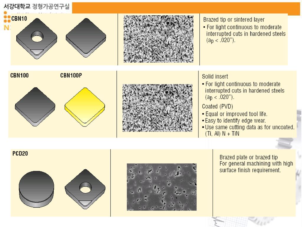
Properties of Cutting Tool Materials
FIGURE Ranges of properties for various groups of cutting-tool materials. (See also Tables 8.1 through 8.5.) FIGURE Construction of polycrystalline cubic-boron-nitride or diamond layer on a tungsten-carbide insert.
 FIGURE 8.39 Construction of polycrystalline cubic-boron-nitride or diamond layer on a tungsten-carbide insert.")
Similar presentations


 화법은 말 그대로 묘사체에 속한다. 작중 인물의 말이나 생각을 작가가 대신해서 묘사하여 전달하는 화법으로서 전달부분이 안 나타 나 있어도.>")
. Carbon nanotube( 탄소 나노튜브 ) Multi-walled carbon nanotube.>")
 1.CVD(Chemical Vapor Deposition), 화학기상증착 기술이란 ? 먼저 CVD 기술을 이해하기 전에 CVD 기술이 반도체 제조공정 중 어디에 위치하고 어떻게 사용되는지를.>")

>")


>")


