Download presentation
Presentation is loading. Please wait.

1
( Foundation for Electronics System Design )
기초 디자인 프로젝트 ( Foundation for Electronics System Design ) 센서부 Sogang Univ. Robot & Vision Lab. September 2007 Byung-Sung Kim
 센서부. Sogang Univ. Robot & Vision Lab. September Byung-Sung Kim.")
2
센서의 역할 센서의 종류 로봇의 환경 정보 획득 (Self-localization, Navigation, etc.)
-벽 정보를 수집한다. 마우스는 미로 내에서 전방과 좌· 우 벽의 유무를 판단하여야 한다. -벽과의 상대적인 거리를 측정하여 자세를 바로잡는데 사용한다. 센서의 종류 적외선 센서 초음파 센서 비젼 센서

3
Intro. Computer Vision Vision Sensor & application
Range Sensor & application Intro. HRV and Application AVS/Intelligent Vehicles Application

4
What is Computer Vision?
A computer sees this. Picture you see. “8” Human 인간은 지능을 가지고 있기 때문에 영상을 보고 바로 이해가 가능하지만, 계산 중심의 Computer는 분석과 해석에 해당하는 처리가 있어야 영상에 대한 이해가 가능하다. “0,1” Computer Computer need an Analysis/Interpreter process

5
What is Computer Vision?
High-level vision, AI, Cognition Computer vision Low level Interm. level Recognition Edge Depth Shape Motion Color Texture Light Grouping Segmentation Surface Volume Reflectance Light Feature models Object models Geometric relations Photometric methods Robotic action, etc. Computer Vision

6
Fields of Computer Vision
Image Processing Pattern Recognition 3D Reconstruction Etc.

7
Image Processing To Process the image to get the information of image
- Feature Extraction - Image Enhancement - Segmentation - Object recognition - etc.

8
Feature Extraction Image Processing Edge Feature extraction extraction
Hough Transform Canny Edge detector Edge extraction Feature extraction Methods - Sobel, Robert, Canny Edge detector etc. Methods - Hough , Wavelet, Fourier Transform

9
Histogram Equalization
Image Processing Image Enhancement Histogram Equalization Noise Remove Many kinds of Noise Adaptive noise filter Sogang Univ. Robot & Vision Lab.

10
Video Analysis Image Processing Motion Tracking Methods
- Optical flow, KLT ( Karhunen - Loeve Transform ), Block Matching etc. Sogang Univ. Robot & Vision Lab.
![]()
11
Pattern Recognition Pattern Classification
Pattern Recognition is concerned with answering the question "What is this? etc.

12
Pattern Recognition Neural Network Statistics Structure

13
Training using Sample data Set Network coefficient
Pattern Recognition Neural Network 1 Training using Sample data Set Network coefficient

14
If fruit Size ‘Big’, P(stawberry)=0.8
Pattern Recognition Statistical Method Camera or other sensor If fruit Color ‘Red’, P(strawberry)=0.33 P(mountain berry)=0.33 P(cherry)=0.33 If fruit Size ‘Big’, P(stawberry)=0.8 Sensing Input Data
=0.33 P(mountain berry)=0.33 P(cherry)=0.33. If fruit Size ‘Big’, P(stawberry)=0.8. Sensing. Input Data.")
15
Pattern Recognition Structual Method
CON (connection) ADJ (adjacent) ABOVE ‘S’, ‘L’, ‘B’ denote side, lake, bay
 ADJ (adjacent) ABOVE. ‘S’, ‘L’, ‘B’ denote side, lake, bay.")
16
3D Reconstruction 2D images or Range Sensor Data → 3D information
Multi-Stripe Projection

17
3D Reconstruction Stereo Vision Right and Left satellite image

18
world Q[24] P[34] Binary-encoded light stripe projection
3D Reconstruction Multi-stripe Projection Yw (Xw , Yw , Zw ) world Xw Q[24] P[34] LCD or DLP y CCD or CMOS x Binary-encoded light stripe projection xp f fp camera (xp) stripe 1-D (x, y ) image 2-D
![world Q[24] P[34] Binary-encoded light stripe projection](http://slidesplayer.org/slide/11178153/60/images/18/world+Q%5B2%EF%82%B44%5D+P%5B3%EF%82%B44%5D+Binary-encoded+light+stripe+projection.jpg "3D Reconstruction. Multi-stripe Projection. Yw. (Xw , Yw , Zw ) world. Xw. Q[24] P[34] LCD or DLP. y. CCD or CMOS. x. Binary-encoded. light stripe. projection. xp. f. fp. camera. (xp) stripe. 1-D. (x, y ) image. 2-D.")
19
color stripes depth VRML view
3D Reconstruction Multi-stripe Projection color stripes depth VRML view (Virtual reality modeling language)
")
20
Intro. Computer Vision Vision Sensor & application II-1. optic camera II-2. IR camera Range Sensor & application Intro. HRV and Application ASV/Intelligent Vehicles Application

21
Image sensor array : light photon convert to Electron
Optical Camera Image sensor array : light photon convert to Electron CCD & CMOS Sensor CCD Sensor : 각 픽셀의 전하패킷을 순차적으로 전하를 전압으로 변환 CMOS Sensor : 전하-전압 변환을 각 픽셀에서 발생

22
A Single View Application
Pattern Recognition Pose Estimation Who? PCA/LDA/ICA

23
A Single View Application
Pattern Recognition

24
Stereo Vision Application
3-D Depth Extraction Known a relative position of two camera Real-time execution for slow to moderate speeds

25
Stereo Vision Application
Test image sequence Right image Disparity map Disparity map : remove occlusion

26
System constitution GPS 수신기 & 안테나 PC 노트북 (거치대 이용) GYRO SENSOR
Car Navigation System System constitution GPS 수신기 & 안테나 차량 전면 대쉬 보드 Serial port 수신 전송속도 : bps(초당 5회) PC 노트북 (거치대 이용) 조수석 설치 CCD 카메라 룸미러 전면부 설치 USB PORT 수신 frame: 30 fps GYRO SENSOR CCD 카메라와 고정 Serial port 수신 Map matching의 정확도 판별.
 PC 노트북 (거치대 이용) 조수석 설치. CCD 카메라. 룸미러 전면부 설치. USB PORT 수신. frame: 30 fps. GYRO SENSOR. CCD 카메라와 고정. Serial port 수신. Map matching의 정확도 판별.")
27
System constitution Lane detection Using image processing
Car Navigation System System constitution Lane detection Using image processing Find Vanishing point & line from lane and Obtain 3D information Matching of 3D information & GPS data & Digital map Display Virtual Object

28
Experiment Results Car Navigation System Lane Detection
GPS + Lane Data

29
Omni-Vision 108° 108° view image 180° view image Spread image
Spread processing

30
Intro. Computer Vision Vision Sensor & application II-1. optic camera II-2. IR camera Range Sensor & application Intro. HRV and Application ASV/Intelligent Vehicles Application

31
Thermal sensitivity : 0.08° Field Of View : 24°X18°
IR Camera Spectral range : 700nm~1300nm Thermal sensitivity : 0.08° Field Of View : 24°X18° Temperature ranges : -40°c to +120°c 0°c to 500°c etc. 적외선은 열을 가지고 있기 때문에 열선으로도 불리기도 한다. 물질이 근적외선을 흡수하면 물질내의 열 운동이 들뜨게 되어 온도가 상승하게 된다.

32
Application – Medical Technology
IR Camera Application – Medical Technology IRIS-5000 신경계질환(Neural Disease), 근 골격계 질환Musculo Skeletal Disease, 갑상선, 부갑상선 질환 등
, 근 골격계 질환Musculo Skeletal Disease, 갑상선, 부갑상선 질환 등.")
33
Application – Building Inspection
IR Camera Application – Building Inspection 건물 부식 부위 검사, 건물 부실 공사 여부 검사 (시멘트 석면 함유량..) 등
 등.")
34
IR Camera Application 화재 발화지 검사 , 방사선 유출 검사 등 안전 및 군사용에 관련하여 다양하게 사용

35
BMW MB S-Class ‘Night Vision’

36
Range Sensor & application
Intro. Computer Vision Vision Sensor & application Range Sensor & application Intro. HRV and Application ASV/Intelligent Vehicles Application

37
LASER Range Finder Scan direction LMS-291(SICK) Max. Range 80m
Application Navigational support/collision prevention Measuring objects Classification of vehicles

38
Vertical 2D laser scanner to acquire geometry
LASER Range Finder buildings vehicle z y x Vertical 2D laser scanner to acquire geometry

39
Vertical 2D laser scanner to acquire geometry
LASER Range Finder buildings vehicle z y x Vertical 2D laser scanner to acquire geometry Synchronised camera to acquire texture

40
world P[34] Q[24] LASER Range Finder Zw Xw (Xw , Yw , Zw ) Yw Xw
fp xp projector LCD or DLP y CCD or CMOS x f camera (xp) stripe 1-D (x, y ) image 2-D
![world P[34] Q[24] LASER Range Finder Zw Xw (Xw , Yw , Zw ) Yw Xw](http://slidesplayer.org/slide/11178153/60/images/40/world+P%5B3%EF%82%B44%5D+Q%5B2%EF%82%B44%5D+LASER+Range+Finder+Zw+Xw+%28Xw+%2C+Yw+%2C+Zw+%29+Yw+Xw.jpg "fp. xp. projector. LCD or DLP. y. CCD or CMOS. x. f. camera. (xp) stripe. 1-D. (x, y ) image. 2-D.")
41
? ? ? ? Vertical 2D laser scanner to acquire geometry
LASER Range Finder ? ? ? z ? y x Vertical 2D laser scanner to acquire geometry Synchronized camera to acquire texture Problem: Localization?

42
Vertical 2D laser scanner to acquire geometry
LASER Range Finder v u z y x Vertical 2D laser scanner to acquire geometry Synchronized camera to acquire texture Problem: Localization? Horizontal 2D scanner

43
LASER Range Finder

44
Ultrasonic application Medical application Navigation or Range Measure
Senscomp, SE-600-E Receiver & Transmitter One body type Separate type : min. 2cm -measured distance : 0.35m~10m Max. no. of measured : 10/sec accuracy : +/- 0.1%

45
초음파 센서 작동 방식 사람 귀에 들리지 않는 20kHz~200kHz 정도의 주파수를 갖는 초음파를 발신하여 그것이 반사되어 되돌아오는 시간을 구하여 반사 물체까지의 거리를 탐지. T/R Object 1 주기 송신부 수신부

46
Ultrasonic Robot Navigation Ultrasonic sensor

47
- Wide Beam, Multi-path, Interference effect
Ultrasonic Problems - Wide Beam, Multi-path, Interference effect ?

48
문제점 방향성의 불확실성 (Angular Uncertainty) 다중 경로 ( Multiple Path )
초음파 센서 문제점 방향성의 불확실성 (Angular Uncertainty) 벽 초음파 센서 이 범위를 감지하므로 벽이 끝나는 지점을 정확히 알기 어렵다. 200kHz 센서 지름 a = 18mm 다중 경로 ( Multiple Path )
 벽. 초음파 센서. 이 범위를 감지하므로 벽이 끝나는 지점을 정확히 알기 어렵다. 200kHz 센서 지름 a = 18mm. 다중 경로 ( Multiple Path )")
49
Short Range Radar 측정 거리 : 0.15m~20m 측정 방위각 : 거리 분해능 :
► 24GHz Radar Sensor 24GHz Radar ( 6cm X 10cm X 2cm ) module 측정 거리 : 0.15m~20m 측정 방위각 : 거리 분해능 :
 module. 측정 거리 : 0.15m~20m. 측정 방위각 : 거리 분해능 :")
50
Short Range Radar 2002, Federal Communications Commission permit to use UWB (Ultra Wide Band) 22~29GHz for Vehicle Radar (ACC) PRE-Crash > 30m 76/77GHz

51
SRR Network Sensor Network

52
SRR Network Multistatic Advantages
- interference avoidance between adjacent radar sensors - accurate timing - utilization of propagation paths between target and different sensors

53
SRR -Object Position

54
SRR –relative velocity
Doppler phenomenon : 측정 대상의 움직임에 따른 radar의 중심 주파수가 shift 되는 현상 Use for -To Extract target radial velocity (range rate) -To Distinguish between moving and stationary target
 -To Distinguish between moving and stationary target.")
55
SRR -Object Position Nearest neighbor data association Object Map

56
적외선 센서 적외선 센서는 발광부와 수광부로 나누어진다.
발광부에서 나온 적외선이 물체에 반사되어 수광부에 얼마나 많은 양이 들어오느냐에 따라서 수광부에 들어오는 전압의 양이 변화하게 된다. 광전효과 아인슈타인이 빛의 입자성을 이용하여 설명한 현상으로 금속 등의 물질에 일정한 진동수 이상의 빛을 비추었을 때, 물질의 표면에서 전자가 튀어나오는 현상이다.

57
구동 방법 적외선 센서 VCC 슈미트 트리거 (파형정형) 입력 포트로 연결 디지털 방식 조정하여 감도를 조절한다.
빛이 들어오면 ‘L’ 디지털 방식 라인트레이서 -> 비교기를 사용하여 수광부에 들어오는 빛에 따른 출력 전압이 기준접압보다 높은 것은 HIGH로 낮은 것은 LOW로 사용하는 방법. VCC 8-bit A/D 변환기 광량에 비례한 전압이 양단에 걸린다. A/D변환 끝 A/D변환 시작 입력포트(8bit) 아날로그 방식 수광부에 들어오는 빛에 따른 출력 전압을 마이크로컨트롤러의 ADC를 통해서 아날로그 값을 디지털 값으로 변환 시키는 방법. 앞의 비교기와는 틀리게 적외선이 반사되는 양이 세분화 되기 때문에 그 값을 가지고 마우스의 거리탐지로 많이 이용
 아날로그 방식. 수광부에 들어오는 빛에 따른 출력 전압을 마이크로컨트롤러의 ADC를 통해서 아날로그 값을 디지털 값으로 변환 시키는 방법. 앞의 비교기와는 틀리게 적외선이 반사되는 양이 세분화 되기 때문에 그 값을 가지고 마우스의 거리탐지로 많이 이용.")
58
PN 접합(Base-Collector)에 생기는 광 전류가 트랜지스터의 Base 전류 역할을 한다.
적외선 센서 수광소자 각종 수광 디바이스의 광 검출 원리와 특징 광 검출의 원리 감도 응답속도 포토 다이오드 PN 접합에 생기는 광 전류 100uA/1000lux 100ns 포토 트랜지스터 PN 접합(Base-Collector)에 생기는 광 전류가 트랜지스터의 Base 전류 역할을 한다. 1mA/100lux 5us 포토 달링턴 트랜지스터 포토 TR과 동일 5mA/20lux 100us CdS 광 에너지에 의한 도전율 변화 E-10 S/1000lux 10ms VCC VCC 출력 500 lux VCC 출력 20 lux VCC 출력 1000 lux 1000 lux 출력 포토 다이오드 포토 트랜지스터 포토 달링턴 트랜지스터 CdS
에 생기는 광 전류가 트랜지스터의 Base 전류 역할을 한다. 1mA/100lux. 5us. 포토 달링턴 트랜지스터. 포토 TR과 동일. 5mA/20lux. 100us. CdS. 광 에너지에 의한 도전율 변화. E-10 S/1000lux. 10ms. VCC. VCC. 출력. 500 lux. VCC. 출력. 20 lux. VCC. 출력 lux lux. 출력. 포토 다이오드. 포토 트랜지스터. 포토 달링턴 트랜지스터. CdS.")
59
발광 센서 원리 : P-N 접합의 소수 캐리어가 주입되어 전자나 정공이 재결합할 때 방출
적외선 센서 발광 센서 녹색 LED 적색LED 파장λ(nm) 적외선LED 상대감도(%) 가시영역 적외선 영역 원리 : P-N 접합의 소수 캐리어가 주입되어 전자나 정공이 재결합할 때 방출 I=10mA (LED에 5~10mA전류를 흘려준다.) 순방향 전압강하 Anode (+) Cathode(-) 그림 1. LED 외형과 전류 제한 저항 값 계산
 적외선LED. 상대감도(%) 가시영역 적외선 영역. 원리 : P-N 접합의 소수 캐리어가 주입되어 전자나 정공이 재결합할 때 방출. I=10mA (LED에 5~10mA전류를 흘려준다.) 순방향 전압강하. Anode (+) Cathode(-) 그림 1. LED 외형과 전류 제한 저항 값 계산.")
60
포토 트랜지스터 : 증폭 전류를 이용하여 출력 전류가 커서 감도가 좋아진다. 그리고 응답속도가 느리다.
적외선 센서 포토다이오드 : 수광량에 비례하여 매우 넓은 Dynamic Range를 얻는다. 그리고 응답속도가 빠른 반면 출력 전류가 작다. 포토 트랜지스터 : 증폭 전류를 이용하여 출력 전류가 커서 감도가 좋아진다. 그리고 응답속도가 느리다. 포토 달링턴 트랜지스터 : 트랜지스터 2단 증폭을 사용하여 감도는 더욱 좋아지고, 응답속도는 더욱 느려진다.

61
► 반응 속도와 감도 포토 다이오드 (SP-1KL) 포토 트랜지스터 (KDTD001) 적외선 센서 포토 다이오드는 직접 측정
100nS~1mS 포토 다이오드 (SP-1KL) 포토 트랜지스터 (KDTD001)
 포토 트랜지스터 (KDTD001)")
62
수광/발광 센서의 Peak wavelength 대역이 일치
적외선 센서 수광/발광 센서의 Peak wavelength 대역이 일치 수광 (ST-7L) 발광 ( EL-7L) 변조를 통한 외란 방지 : 펄스 점등 방식 (Pulse Drive) DC 성분으로 송수신 시, 외란으로 인한 오동작 : High Pass Filter 를 통한 외란(DC성분) 제거
 발광 ( EL-7L) 변조를 통한 외란 방지 : 펄스 점등 방식 (Pulse Drive) DC 성분으로 송수신 시, 외란으로 인한 오동작. : High Pass Filter 를 통한 외란(DC성분) 제거.")
63
적외선 센서 수광 센서 회로부 HPF (High Pass Filter) HPF (High Pass Filter)+증폭 회로
 HPF (High Pass Filter)+증폭 회로")
64
측방/대각 센서 – 수광: 빔폭이 좁은게 좋다. (가까이 갈수록 커지다가 일정이상 가까워지면 줄어든다.)
적외선 센서 보통 비교적 밝은 조명 아래에서 동작하므로 외란 등에 오동작을 일으키지 않도록 발광부의 출력은 충분히 크게 하고, 상대적으로 수신부의 감도는 작게한다. 전방 센서 – 수광 : 빔폭이 넓은게 좋다. 측방/대각 센서 – 수광: 빔폭이 좁은게 좋다 (가까이 갈수록 커지다가 일정이상 가까워지면 줄어든다.)
")
65
A/D 컨버터 소개 ATmega 128의 경우 10 비트 축차 근사형의 A/D 컨버터를 8개 내장하고 있다. 실질적으로 A/D 컨버터는 한 개이며, 채널을 바꿔가며 아날로그 신호를 입력받을 수 있다. A/D 컨버터를 제어하기 위한 레지스터로는 아날로그 디지털 멀티플렉서 선택 레지스터(ADMUX)와 아날로그 디지털 컨버터 제어 상태 레지스터(ADCSR)가 있다. ADMUX는 A/D신호를 입력 받을 채널을 0~7까지 선택한다. ADCSR을 설정하여 컨버전 프리스케일러 설정, 컨버터 완료 인터럽트를 설정한다. 모든 설정이 끝나면 전역 인터럽트 플래그를 ‘셋’하여 인터럽트를 활성화한다. 아날로그 디지털 변환 완료 인터럽트 처리 루틴을 구성한 후, ADCSR의 6번 비트를 셋시켜 A/D 변환을 시작하게 한다.
와 아날로그 디지털 컨버터 제어 상태 레지스터(ADCSR)가 있다. ADMUX는 A/D신호를 입력 받을 채널을 0~7까지 선택한다. ADCSR을 설정하여 컨버전 프리스케일러 설정, 컨버터 완료 인터럽트를 설정한다. 모든 설정이 끝나면 전역 인터럽트 플래그를 ‘셋’하여 인터럽트를 활성화한다. 아날로그 디지털 변환 완료 인터럽트 처리 루틴을 구성한 후, ADCSR의 6번 비트를 셋시켜 A/D 변환을 시작하게 한다.")
66
< A/D 컨버터 기준전압 선택 >
ADMUX (ADC Multiplexer Selection Register) REFS1 REFS0 기준전압 외부의 AREF 단자로 입력된 전압을 사용한다. 1 외부의 AVCC 단자로 입력된 전압을 사용한다. * (reserved) 내부의 2.56V를 사용한다. * * 의 경우에는 AREF 단자와 접지 사이에 콘덴서를 접속할 것. < A/D 컨버터 기준전압 선택 > ADLAR (ADC Left Adjust Result) : ‘1’로 지정하면 변환 결과가 ADC 데이터 레지스터에 저장될 때의 방향순서 결정 ADLAR=1 ADLAR=0
 REFS1. REFS0. 기준전압. 외부의 AREF 단자로 입력된 전압을 사용한다. 1. 외부의 AVCC 단자로 입력된 전압을 사용한다. * (reserved) 내부의 2.56V를 사용한다. * * 의 경우에는 AREF 단자와 접지 사이에 콘덴서를 접속할 것. < A/D 컨버터 기준전압 선택 > ADLAR (ADC Left Adjust Result) : ‘1’로 지정하면 변환 결과가 ADC 데이터 레지스터에 저장될 때의 방향순서 결정. ADLAR=1. ADLAR=0.")
68
< A/D 컨버터 클럭의 분주비 선택 >
ADCSRA (ADC Control and Status Register A) Bit 7 – ADEN (ADC Enable) : Set(1) -> ADC 활성화 Bit 6 – ADSC (ADC Start Conversion) : Set -> ADC 변환 시작 (단일 변환 모드일 때, 단 한번만 작동/ 프리런닝 모드일 때, 반복 동작) Bit 5 – ADFR (ADC Free Running Select) : (1) -> 프리러닝 모드 , (0) -> 단일 변환 모드 Bit 4 – ADIF (ADC Interrupt Flag) : ADC 변환완료 인터럽트가 요청되고 그 상태를 이 비트에 표시한다. Bit 3 – ADIE (ADC Interrupt Enalbe) : Set-> ADC Interrupt 활성화 Bit 2,1,0 – ADPS 2~0 (ADC Prescaler Select Bit) : ADC에 인가되는 클릭의 분주비를 설정하다. < A/D 컨버터 클럭의 분주비 선택 >
 Bit 7 – ADEN (ADC Enable) : Set(1) -> ADC 활성화. Bit 6 – ADSC (ADC Start Conversion) : Set -> ADC 변환 시작 (단일 변환 모드일 때, 단 한번만 작동/ 프리런닝 모드일 때, 반복 동작) Bit 5 – ADFR (ADC Free Running Select) : (1) -> 프리러닝 모드 , (0) -> 단일 변환 모드. Bit 4 – ADIF (ADC Interrupt Flag) : ADC 변환완료 인터럽트가 요청되고 그 상태를 이 비트에 표시한다. Bit 3 – ADIE (ADC Interrupt Enalbe) : Set-> ADC Interrupt 활성화. Bit 2,1,0 – ADPS 2~0 (ADC Prescaler Select Bit) : ADC에 인가되는 클릭의 분주비를 설정하다. < A/D 컨버터 클럭의 분주비 선택 >")
69
A/D Converter의 동작

70
① A/D Converter의 초기화 설정 ② A/D Converter 작동 ADC 활성화 (ADEN=1)
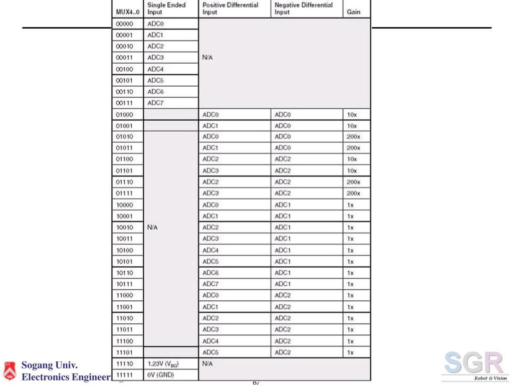
ADC 클럭 설정 (ADPS 2~0) ADC 기준전압 설정 (REF 1~0) ADC 입력채널 설정 (MUX 4~0) ADC 동작모드 설정 (ADFR) ADC 변환 완료 인터럽트 활성화 (ADIE) ② A/D Converter 작동 ADC 시작신호 (ADSC)
 ADC 기준전압 설정 (REF 1~0) ADC 입력채널 설정 (MUX 4~0) ADC 동작모드 설정 (ADFR) ADC 변환 완료 인터럽트 활성화 (ADIE) ② A/D Converter 작동. ADC 시작신호 (ADSC)")
71
③ A/D 변환 ④ A/D 변환 완료 ⑤ A/D 변환 완료 인터럽트 요청 ⑥ ADC 상태 플래그 셋 ⑦ ADC 다음 동작 결정
[단극성 입력] [차동 입력] ④ A/D 변환 완료 ADC 변환이 완료되면 변환 값을 ADCH/L 에 저장하게 된다. ⑤ A/D 변환 완료 인터럽트 요청 ADC Conversion Complete Interrupt 요청 ⑥ ADC 상태 플래그 셋 AIDF = 1 ⑦ ADC 다음 동작 결정 단일/연속동작인지 구분하여 다음 동작 수행을 결정한다. (ADFR)
")
72
- A/D Convertor 잡음 제거 방법 A/D Convertor의 경우에는 노이즈에 매우 민감하기 때문에 ATmega128 내에서도 AVCC, AREF, AGND와 같은 ADC전원 구성도 따로 하였으며 사용자 또한 몇가지 사항을 주의하여 사용해야한다. - AVCC = 독립적인 아날로그 회로 전원 단자 - AREF = 기준 전원 입력 단자 - AGND = 아날로그 회로 접지 단자 AVCC의 LC필터를 통한 VCC인가 방법

73
-End-

Similar presentations

 Sele-Call Radio Buoy transmits answer signal when mother vessel calls via THR- L400 / THR-L400-II with SSB radio.>")


>")


 2008.10.28 박사 과정 이종환 011.9640.5025 leejh@astro.snu.ac.kr.>")

.>")

