Download presentation
Presentation is loading. Please wait.

1
DSP based Data Acquisition Board
교육 교재(#01) 동 명 전 자 대구광역시 동구 신천4동 ( TEL: 053) / FAX: 053)
 동 명 전 자. 대구광역시 동구 신천4동 ( TEL: 053) / FAX: 053)")
2
1. DSP 1) 왜 DSP냐? Digital signal processing에 있어서는 일반 CPU에 비해 최소 수십배에서 최대 수백배의 성능을 발휘 2) DSP 사용 예제 (1) 오디오의 Mode효과 극장식 효과음, 운동장식 효과음, Jazz 효과 , Classic 효과 (2) 휴대폰 Analog 휴대폰에서는 1주파수에 1명의 가입자가 사용하지만 Digital 휴대폰에서는 1주파수에 10명의 가입자가 사용함 (3) TV, Digital Camcord 화면이 찌그러지는 잡음 부분을 DSP가 계산하여 교정시킴 (4) 휴대폰 Test Set (HP > HPE8285)에 DSP를 적용함으로 Test 시간 감소 3) 전자 신문의 DSP 란? (newspaper.ppt) 4) TI Homepage의 DSP Overview (ti_dsp.ppt) 5) TI.korea Hopepage의 DSP와 TI (ti_korea.ppt) 2. Ti DSP의 종류
 오디오의 Mode효과. 극장식 효과음, 운동장식 효과음, Jazz 효과 , Classic 효과. (2) 휴대폰. Analog 휴대폰에서는 1주파수에 1명의 가입자가 사용하지만. Digital 휴대폰에서는 1주파수에 10명의 가입자가 사용함. (3) TV, Digital Camcord. 화면이 찌그러지는 잡음 부분을 DSP가 계산하여 교정시킴. (4) 휴대폰 Test Set (HP > HPE8285)에 DSP를 적용함으로. Test 시간 감소. 3) 전자 신문의 DSP 란 (newspaper.ppt) 4) TI Homepage의 DSP Overview (ti_dsp.ppt) 5) TI.korea Hopepage의 DSP와 TI (ti_korea.ppt) 2. Ti DSP의 종류.")
3
3) DSP가 Old Model 회로(pic, dtmf decode, dtmf encode)의 일을 Digital Signal
3. ARS BOARD에 DSP를 적용한 예제 1) OLD MODEL cpu Codec pic Dtmf decode Dtmf encode 위 회로와 동일 전화선 PC memory 2) NEW MODEL dsp Codec 전화선 PC memory 3) DSP가 Old Model 회로(pic, dtmf decode, dtmf encode)의 일을 Digital Signal Processing으로 대체함. (1) 부품 단가가 50% 낮아짐 : 부품단가(pic, dtmf decode, dtmf encode)가 고가임 (2) 성능은 2배임 : channel 수의 배가 (3) Software만 교체함으로 타 기능 추가도 가능 : 다자간통신, Fax, Keyphone (4) Software와 Hardware를 조금만 수정하면 Channel 수 증가 가능 (5) 회로가 간단해져 유지보수가 쉬움
 OLD MODEL. cpu. Codec. pic. Dtmf decode. Dtmf encode. 위 회로와 동일. 전화선. PC. memory. 2) NEW MODEL. dsp. Codec. 전화선. PC. memory. 3) DSP가 Old Model 회로(pic, dtmf decode, dtmf encode)의 일을 Digital Signal. Processing으로 대체함. (1) 부품 단가가 50% 낮아짐 : 부품단가(pic, dtmf decode, dtmf encode)가 고가임. (2) 성능은 2배임 : channel 수의 배가. (3) Software만 교체함으로 타 기능 추가도 가능 : 다자간통신, Fax, Keyphone. (4) Software와 Hardware를 조금만 수정하면 Channel 수 증가 가능. (5) 회로가 간단해져 유지보수가 쉬움.")
4
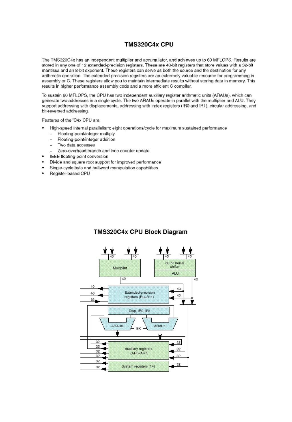
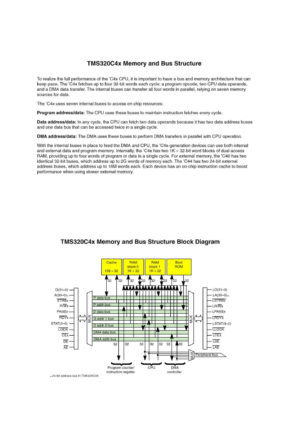
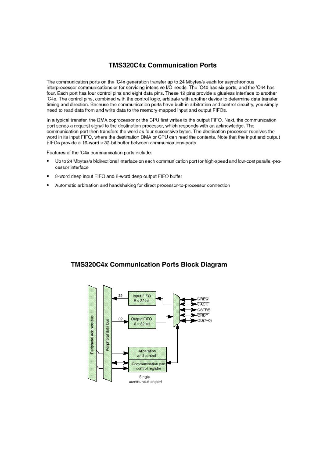
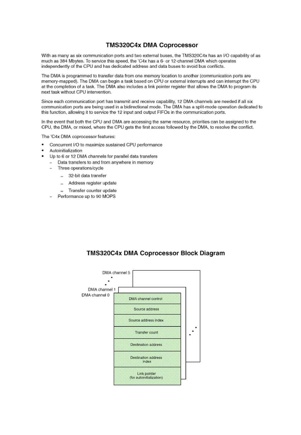
4. DSP 구조 (개괄 설명)
")
9
5. The TMS320 Development Tools
1) Overview 2) The TMS320C4x Development Tools
 Overview. 2) The TMS320C4x Development Tools.")
10
3) TMS320 Development Tool Summary
Assembler/ Linker: Available for all TMS320 devices, the assemblers and linkers are code- generation tools that convert TMS320 assembly language source files into executable object code. These are included in EVMs and C compiler packages. C compiler: Available for the 'C2xx, 'C3x, 'C4x, 'C5x, 'C54x, 'C6x, and 'C8x, the TMS320 C compiler translates ANSI- standard C language files into highly- efficient TMS320 assembly language source files. The C compiler includes an assembler/ linker. Simulator: Available for all TMS320 devices, the simulator is a software program that simulates the TMS320 microcontroller and microprocessor modes for cost- effective, non- real- time development. With the inexpensive software simulator, you can debug without target hardware. The simulator includes the high- level- language (HLL) debug interface. Evaluation module (EVM): EVMs are PC add- in boards that include the target processor, a small amount of memory, and limited peripherals. This allows you to run code in real time and interface to an external system. The EVM includes the HLL debug interface and the assembler/ linker. Emulators (XDS ):The 'C2xx, 'C3x, 'C4x, 'C5x, 'C54x, 'C6x, and 'C8x use a scan- based technology for emulation with the XDS510PP/ 510WS. The emulators include the HLL debug interface. DSP starter kit (DSK): Low- cost, simple, stand- alone application board that lets you experiment with either 'C24x, 'C3x, 'C5x, 'C54x, or 'C6x DSPs for real- time signal processing. The DSK board comes with a debugger and limited assembler. Parallel processing development system (PPDS): The PPDS is a standalone TMS320C4x target board that allows you to develop, run, and debug a system with four 'C4x devices. For a complete system, the XDS510
 debug interface. Evaluation module (EVM): EVMs are PC add- in boards that include the target processor, a small amount of. memory, and limited peripherals. This allows you to run code in real time and interface to an external system. The EVM includes the HLL debug interface and the assembler/ linker. Emulators (XDS ):The C2xx, C3x, C4x, C5x, C54x, C6x, and C8x use a scan- based technology for. emulation with the XDS510PP/ 510WS. The emulators include the HLL debug interface. DSP starter kit (DSK): Low- cost, simple, stand- alone application board that lets you experiment with either. C24x, C3x, C5x, C54x, or C6x DSPs for real- time signal processing. The DSK board comes with a debugger. and limited assembler. Parallel processing development system (PPDS): The PPDS is a standalone TMS320C4x target board that. allows you to develop, run, and debug a system with four C4x devices. For a complete system, the XDS510.")
11
6. PCI BUS Controller Chip
1) 회사 분류 (1) PLX : PLX 9050, PLX 9080외 (2) V3Semiconductor : EPC360외 (3) Altera : Max-xxxx외 2) V3 EPC360 Block Diagram
 회사 분류. (1) PLX : PLX 9050, PLX 9080외. (2) V3Semiconductor : EPC360외. (3) Altera : Max-xxxx외. 2) V3 EPC360 Block Diagram.")
12
3) V3 EPC360 적용 예제 4) V3 EPC360 개괄 설명 (1) Direct Local Bus Write to PCI Space * Local-to-PCI aperture. * local bus writes with an address within the range E H to E03F.FFFFH (base at E H with 4 megabyte window), will be "captured" and converted to PCI bus A H to A03F.FFFFH * Write to location E H in local space, into a write to location A H in PCI space. (2) Direct Local Bus Read from PCI Space (3) PCI Write to Local Space * PCI-to-Local busapertures (4) PCI Reads from Local Space (5) DMA Transfers * DMA, 256 Byte fifo (6) Mailbox Registers and Doorbell Interrupts (7) Internal Register Apertures
, will be captured and. converted to PCI bus A H to A03F.FFFFH. * Write to location E H in local space, into a write to location. A H in PCI space. (2) Direct Local Bus Read from PCI Space. (3) PCI Write to Local Space. * PCI-to-Local busapertures. (4) PCI Reads from Local Space. (5) DMA Transfers. * DMA, 256 Byte fifo. (6) Mailbox Registers and Doorbell Interrupts. (7) Internal Register Apertures.")
13
Serial-Parallel Interface Logic
7. 개발 Board Block Diagram 32 RESET Vector Sel. Rom Enable Sel. Local SRAM (64K * 32) A30-A0 /CS /WE D31-D0 40MHz OSC Divide T0 T1 T# Counter Timer PLD 7 31 TMS320C40 /GSTB0 GR/W0 GRDY0 RESET RESETLOC0 RESETLOC1 ROMEN X2/CLKIN LA30-A0 LD31-D0 /LSTB0 LR/W0 LRDY0 /LSTB1 LR/W1 LRDY1 JTAG COMM PORT0 - PORT5 Control Signal EPROM A15-A0 /OE << /EPROM_CS << /RAM_CS << /RAM_WE << /EPROM_OE Interface >> /EPROM_CS >> /RAM_CS >> /RAM_WE >> /EPROM_OE >> CNTL# >>/EE_WRITE_EN Control 3. Interrupt Cont 1.Addr decode 2. PCI Control 4. Etc Control Global SRAM (256K * 32) AD9851 DDS EEPROM CS SK SO SI << /EE_WRITE_EN Com Port 0 Bi-Directional Serial-Parallel Interface Logic 4CH-MUX Com Port 1 Interface Logoc Com Port 2 Interface Logic ADS 821 10Bit 40Mhz A/D Converter 10 PCI Controller A16-A0 (256Bit) D/A Converter 4CH
 A30-A0. /CS. /WE. D31-D0. 40MHz. OSC. Divide. T0. T1. T# Counter. Timer. PLD TMS320C40. /GSTB0. GR/W0. GRDY0. RESET. RESETLOC0. RESETLOC1. ROMEN. X2/CLKIN. LA30-A0. LD31-D0. /LSTB0. LR/W0. LRDY0. /LSTB1. LR/W1. LRDY1. JTAG. COMM PORT0 - PORT5. Control Signal. EPROM. A15-A0. /OE. << /EPROM_CS. << /RAM_CS. << /RAM_WE. << /EPROM_OE. Interface. >> /EPROM_CS. >> /RAM_CS. >> /RAM_WE. >> /EPROM_OE. >> CNTL# >>/EE_WRITE_EN. Control. 3. Interrupt Cont. 1.Addr decode. 2. PCI Control. 4. Etc Control. Global SRAM. (256K * 32) AD9851 DDS. EEPROM. CS. SK. SO. SI. << /EE_WRITE_EN. Com Port 0. Bi-Directional. Serial-Parallel Interface Logic. 4CH-MUX. Com Port 1. Interface Logoc. Com Port 2. Interface Logic. ADS Bit 40Mhz. A/D Converter. 10. PCI Controller. A16-A0. (256Bit) D/A Converter. 4CH.")
14
8. Vxd 란 ? - Virtual x Device Driver (VKD, VMDAD) 9. VHDL 이란 ? - VHDL : VHSIC[Very High Integrated Circuit] Hardware Description Language - PLD : Programmable Logic Device - Tool : Altra Max Plus2 - 추후 Design 예제 표준 Bus Bus Controller Processor PLD ………... 기능1 기능2 기능n 10. 향후 교육 방향 토의 -
![8. Vxd 란 - Virtual x Device Driver (VKD, VMDAD) 9. VHDL 이란 - VHDL : VHSIC[Very High Integrated Circuit] Hardware Description Language.](http://slidesplayer.org/slide/13559962/82/images/14/8.+Vxd+%EB%9E%80+-+Virtual+x+Device+Driver+%28VKD%2C+VMDAD%29+9.+VHDL+%EC%9D%B4%EB%9E%80+-+VHDL+%3A+VHSIC%5BVery+High+Integrated+Circuit%5D+Hardware+Description+Language..jpg "- PLD : Programmable Logic Device. - Tool : Altra Max Plus2. - 추후 Design 예제. 표준 Bus. Bus. Controller. Processor. PLD. ………... 기능1. 기능2. 기능n. 10. 향후 교육 방향 토의. -")
Similar presentations


>")

>")


>")

.>")

 Slide 1 (of 15).>")


>")